What happens when a customer’s drawing defines the dimensions but leaves the surface treatment blank? Should a manufacturer simply follow the drawing, or should it review how the different metals will perform in the complete assembly? Can a new supplier convert separate 2D parts into a production-ready sliding roller without changing the customer’s intended structure?
We faced these questions during the development of this custom sliding roller for a Russian customer.
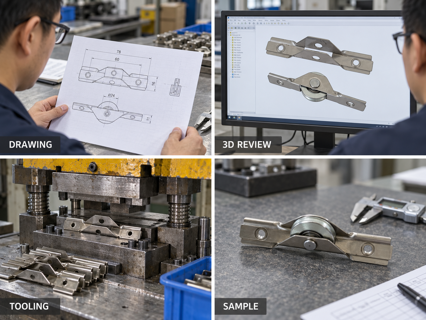
The customer sent us a 2D drawing for a new roller assembly. This was our first project together. We first confirmed the materials, product scope and quotation. We then modelled every component and prepared a complete 3D assembly for the customer to review.
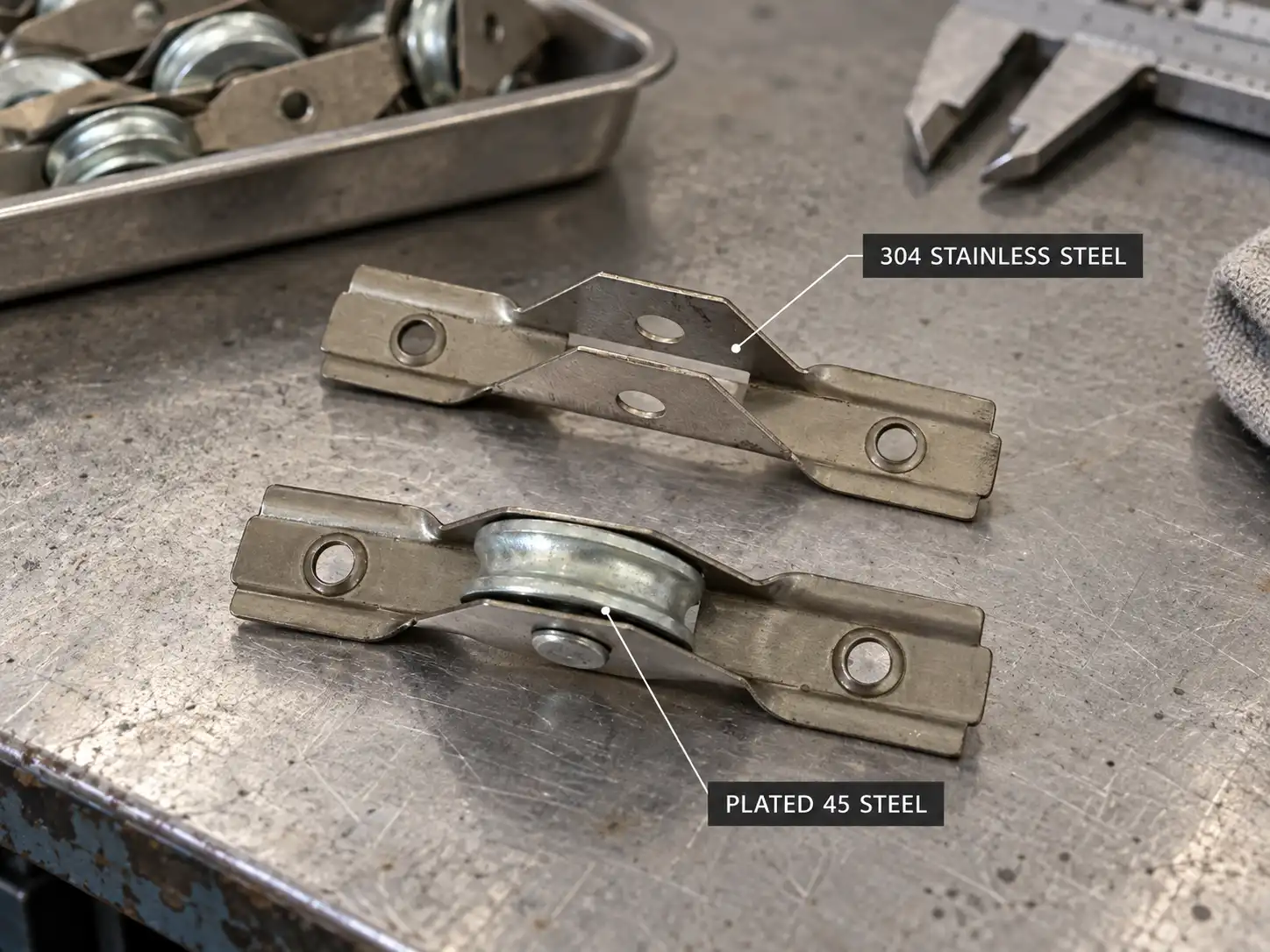
During sampling, we found one detail that needed more attention. The outer housing used 304 stainless steel, while several internal parts used 45 steel. The drawing did not specify any surface treatment for these carbon-steel components.
I understood why the customer selected 304 stainless steel for the housing. Corrosion resistance was clearly part of the product requirement. Leaving the 45 steel parts untreated could work against that goal, especially if moisture entered the assembly.
We therefore proposed an electroplated finish for the relevant components. We included this upgrade without increasing the agreed price.
This project was not only about making every part to the stated dimensions. We needed to make sure the materials, finish, assembly and production route supported the same product goal.
This case shows how we manage an OEM sliding roller project from drawing review and 3D modelling to tooling, sampling and production approval.
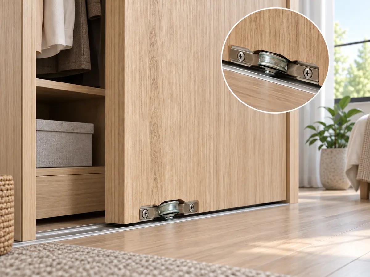
What Does This Custom Sliding Roller Case Study Cover?
This case study explains how we reviewed the customer’s 2D drawing, created a complete 3D assembly, opened the tooling and identified a missing surface-treatment requirement during sampling.
It is written for:
- Door and window manufacturers
- Sliding system brands
- Hardware importers
- Building hardware distributors
- OEM sourcing teams
- Product managers
- Purchasing staff
- Quality engineers
- Companies developing custom rollers, brackets and bearing pulleys
This is a real manufacturing case. I have removed the customer’s name, confidential dimensions and other commercially sensitive information.
What Did the Russian Customer Ask Us to Develop?
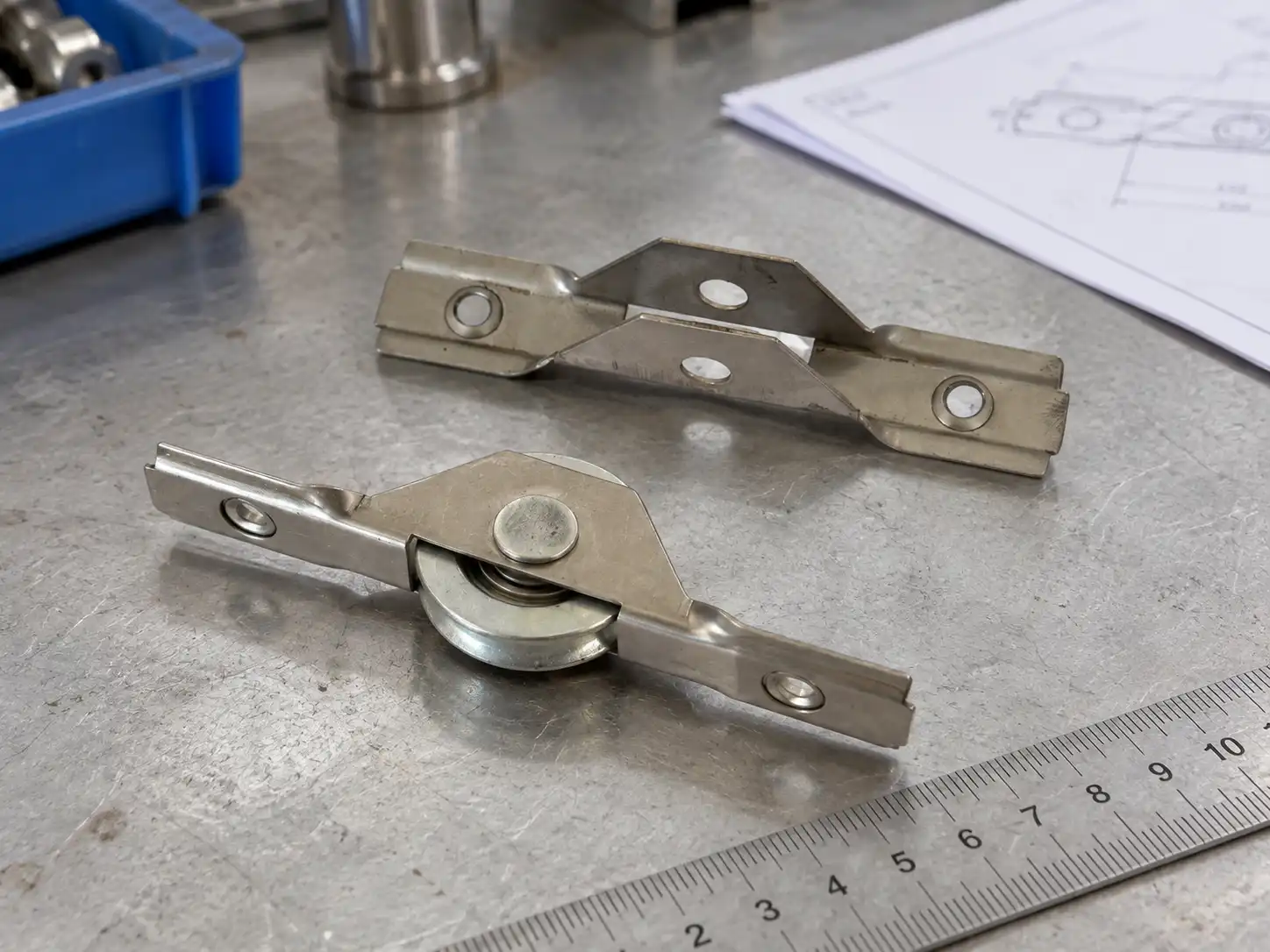
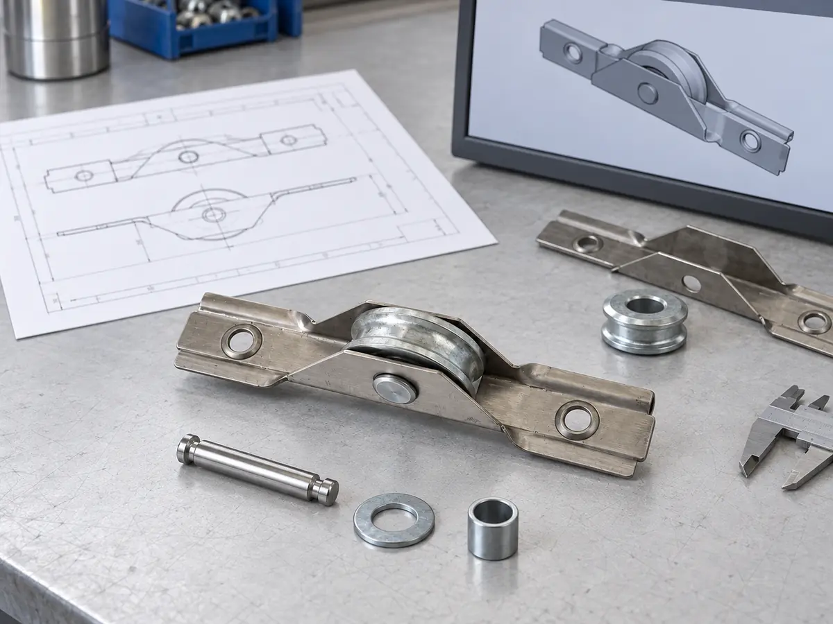
The Russian customer asked us to manufacture a complete custom sliding roller assembly from a supplied 2D drawing. The product included a formed outer housing, a wheel, a shaft and several connected metal components.
This was not a standard catalogue product. The roller needed a specific housing shape, mounting position, wheel location and internal structure.
The drawing gave us the main dimensions and material requirements. It specified 304 stainless steel for the outer housing and 45 steel for several other parts.
Our first task was to separate the assembly into manufacturable components.
| Component area | What we reviewed |
|---|---|
| Outer housing | 304 stainless steel, formed shape and mounting holes |
| Wheel | Profile, diameter, running surface and installed position |
| Shaft or rivet | Material, dimensions and retention method |
| Internal parts | 45 steel, fit and movement |
| Connection points | Hole positions, riveting and assembly clearance |
| Complete assembly | Rotation, alignment and overall dimensions |
A 2D drawing can show dimensions and materials clearly. However, it may not show every production decision or the complete relationship between the parts.
We still needed to determine:
- How the stamped housing would be formed
- How the wheel would sit inside the housing
- How the shaft would retain the wheel
- Which clearances controlled rotation
- Which dimensions controlled installation
- How the complete product would be assembled
- Which surfaces needed additional protection
For a custom sliding roller, installation dimensions and movement dimensions are equally important. A roller may match the mounting holes but place the wheel at the wrong height. It may rotate smoothly but fail to fit the customer’s frame.
Why Did We Confirm the Material and Quotation First?
We confirmed the main materials and quotation before detailed 3D modelling because material selection affects tooling, forming, machining, finishing and total production cost.
The customer had already selected the main materials. We reviewed whether those materials suited the proposed production route.
The housing used 304 stainless steel. Several internal parts used 45 steel, which is a medium-carbon steel selected for suitable strength and machining performance in many mechanical components.
At this stage, I checked:
- Material grade
- Material thickness
- Part dimensions
- Stamping requirements
- Machining requirements
- Wheel structure
- Shaft and rivet structure
- Assembly method
- Expected order quantity
- Tooling requirements
- Sample requirements
- Packaging expectations
This review helped us prepare a quotation for the complete assembly rather than one visible housing.
For custom hardware, an unclear quotation can create problems later. One supplier may quote only the stamped housing. Another may include the wheel, shaft, surface treatment, assembly and inspection.
The two prices would not represent the same product.
Our quotation therefore needed to define the complete scope.
| Quotation item | What we confirmed |
|---|---|
| Product scope | Complete custom sliding roller assembly |
| Materials | 304 stainless steel and 45 steel parts |
| Tooling | Required forming and production tooling |
| Components | Housing, wheel, shaft and connected parts |
| Assembly | Riveting and complete product assembly |
| Samples | Trial products for customer confirmation |
| Surface finish | Reviewed again during sample production |
| Bulk production | Started only after sample approval |
We did not treat the material list as the final production instruction. We treated it as the starting point for a complete manufacturing review.
Why Did We Create a 3D Assembly From the 2D Drawing?
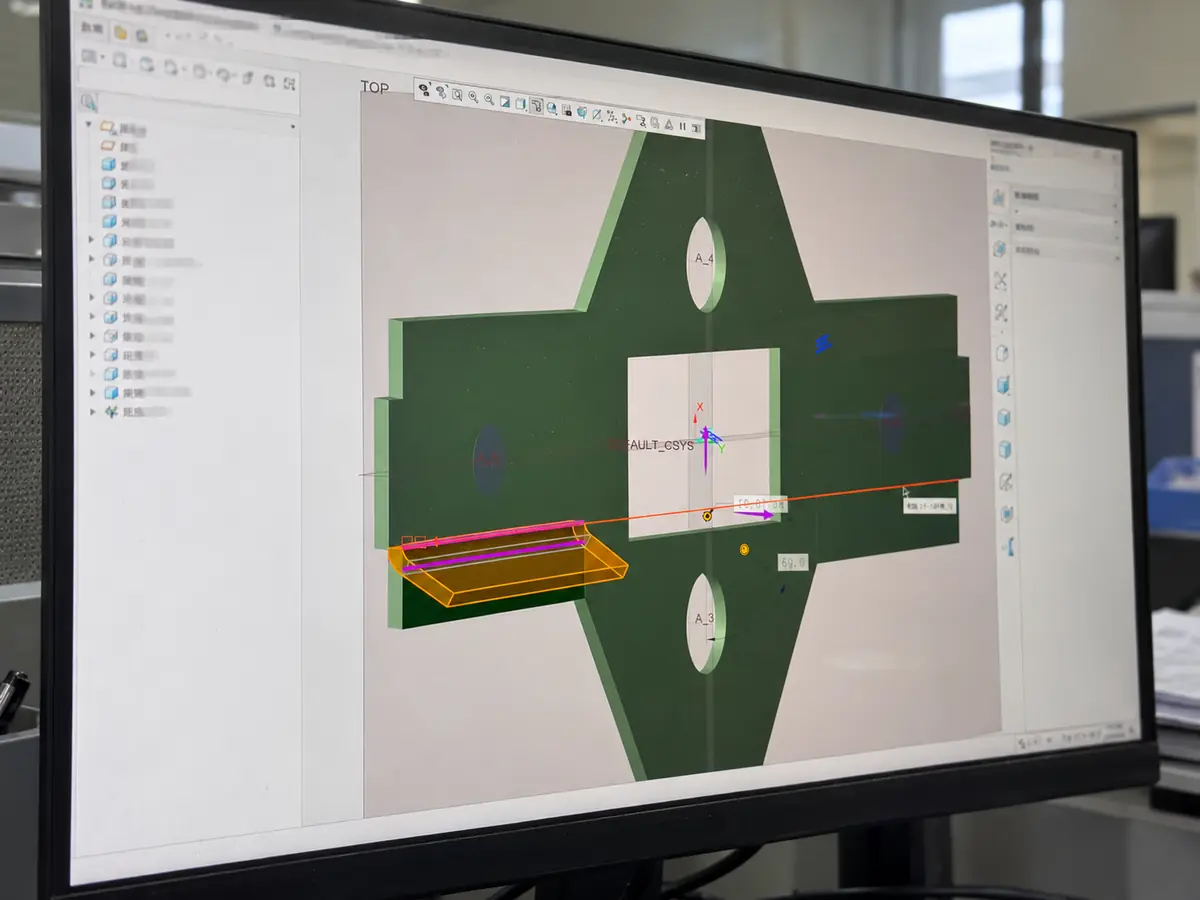
We created a 3D assembly so the customer could review how every component fitted together before we opened the mould and produced the tooling.
This step gave both sides a clearer view of the finished product.
A 2D drawing may show separate views, materials and dimensions. A 3D model helps us check:
- Whether components interfere with one another
- Whether the wheel sits in the correct position
- Whether the shaft passes through the intended parts
- Whether the housing leaves enough rotation clearance
- Whether the mounting holes align
- Whether the formed sections can be produced
- Whether the assembly direction is practical
- Whether the finished product matches the customer’s concept
I do not use a 3D model only to make a quotation look more complete. I use it to reduce uncertainty before tooling.At the same time, I hope to understand the client's design philosophy and confirm whether it has been consistent with our mold master
For this project, we modelled the individual components and then built the complete assembly. We sent the 3D views to the customer for confirmation.Including internal built-in bearings, shaft sleeves, shafts, and casings.
The bending degree, sinking screw direction, and punching type of each accessory are all things we need to confirm.
| Development stage | Main purpose |
|---|---|
| Customer’s 2D drawing | Defines the intended dimensions and structure |
| Component review | Separates the assembly into manufacturable parts |
| 3D part modelling | Checks shapes, bends and interfaces |
| 3D assembly | Checks fit, position, clearance and assembly |
| Customer confirmation | Approves the structure before tooling |
| Tooling drawing | Converts the approved structure into production tools |
The 3D assembly did not replace the approved 2D drawing. The 2D drawing still controlled the agreed dimensions and materials.
What Did We Check Before Opening the Mould?
Before opening the mould, we checked the approved structure, part interfaces, forming route, assembly space and foreseeable production risks.
Tooling is an important cost in a custom sliding roller project. Once the tooling has been made, a structural change may require modification or a new tool.
I therefore wanted the main questions settled before production started.
Which Dimensions Controlled Installation?
We identified the dimensions that affected the customer’s installation:
- Overall length
- Overall width
- Housing height
- Mounting-hole diameter
- Mounting-hole spacing
- Wheel position
- Installed wheel height
- Bracket width
- Available assembly clearance
Which Dimensions Controlled Movement?
We also identified the dimensions that affected roller operation:
- Wheel diameter
- Wheel width
- Wheel profile
- Shaft diameter
- Shaft position
- Side clearance
- Housing clearance
- Rivet position
- Wheel alignment
Which Parts Needed Tooling?
The housing used formed metal parts, so we reviewed:
- Blank shape
- Bend position
- Hole position
- Forming sequence
- Riveting access
- Part removal from the tool
- Expected production repeatability
After the structure and 3D assembly were confirmed, we started tooling and sample production.
This sequence reduced the chance of opening a mould for a structure that the customer had not fully reviewed.
What Issue Did We Find During Sliding Roller Sampling?
During sampling, we found that the drawing specified 304 stainless steel for the outer housing and 45 steel for other parts, but it did not define a surface treatment for the 45 steel components.
This was not a dimensional error. It was an undefined material-protection requirement.
The components could still be manufactured from the stated materials. The assembly could also be completed. However, we needed to decide how the carbon-steel parts should be protected.
The material combination was:
| Component group | Drawing material | Surface treatment shown |
|---|---|---|
| Outer housing | 304 stainless steel | No additional treatment specified |
| Internal metal parts | 45 steel | Not specified |
| Shaft or rivet parts | 45 steel or related steel | Not specified |
| Wheel assembly | Based on approved design | Reviewed as part of the complete product |
I considered the likely product requirement.
The customer had selected 304 stainless steel for the housing. This suggested that corrosion resistance and product appearance mattered to the project.
If the 45 steel components remained untreated, they could rust before the stainless steel housing showed a similar change, especially if moisture entered the internal assembly.
I did not want to assume that the customer intended to leave those components untreated simply because the drawing contained no finishing note.
I also did not want to replace the 45 steel with stainless steel without approval. A material change could affect:
- Strength
- Hardness
- Machining
- Forming
- Riveting
- Wear
- Cost
The more controlled route was to keep the approved base materials and propose a protective surface treatment for the carbon-steel parts.
Why Did the 45 Steel Parts Need Surface Treatment?
The 45 steel parts needed a protective finish because bare carbon steel has a different corrosion response from 304 stainless steel. The mixed-material assembly needed one clear environmental requirement.
The stainless steel housing gave the outside of the product better corrosion resistance than an untreated carbon-steel housing under many normal conditions.
The internal 45 steel parts served a different purpose. They provided suitable mechanical and processing properties for the approved structure.
Both material choices could make sense, but their surface conditions needed to support the same product requirement.
Without a defined finish, the product could face several risks:
- Internal components could develop visible rust
- Corrosion could appear around holes and contact areas
- The product appearance could become inconsistent
- Moisture could affect parts that the stainless housing did not protect
- Different production batches could receive different finishes
- The product could meet the dimensional drawing but miss the intended environmental performance
We therefore proposed electroplating for the relevant carbon-steel parts.
The plating added a protective layer and produced a more consistent appearance across the assembly.
However, electroplating does not make the complete roller corrosion-proof. The final result still depends on:
- Plating type
- Coating thickness
- Surface preparation
- Coverage
- Contact areas
- Storage
- Packaging
- Humidity
- Water exposure
- Salt exposure
- Installation conditions
I would not claim that this treatment makes the roller suitable for every outdoor, coastal or high-salt application.
If a buyer requires a defined corrosion level, the project should include a clear test method and acceptance requirement.
Why Did We Not Change Every Part to 304 Stainless Steel?
Changing every component to stainless steel may sound like a simple solution, but it was not the structure approved by the customer.
Because we need to consider the cost of the product and the machining of accessories. We only made minor changes to the original drawing requirements and did not intend to alter the customer's initial requirements
Our proposal kept the original material concept and added protection where the drawing had left a gap.
This was a controlled production improvement rather than an unapproved redesign.
Why Did We Offer the Upgrade Without Increasing the Price?
We kept the original quoted price because this was our first project with the customer, and we wanted the approved sample to reflect the intended product quality.
We had already reviewed the roller as a complete assembly. The surface treatment supported the customer’s likely corrosion-resistance requirement and reduced the risk of supplying untreated carbon-steel components inside a stainless steel housing.
I considered this part of our responsibility during product development.
This does not mean that every future material or process change should be free. New tooling, major design changes, special testing and different materials can affect the quotation.
In this case, the upgrade was limited and manageable. We could include it without changing the agreed price.
The important point was not the additional processing cost. The important point was that the customer needed a suitable sample for approval.
A first sample can affect:
- Customer confidence
- Installation testing
- Corrosion review
- Appearance approval
- Future product specifications
- Repeat-production control
If we had supplied untreated internal parts, the customer might have approved the dimensions but later reported corrosion. Both sides would then need another review, another sample and possibly another shipment.
The surface-treatment upgrade helped aviod what our customer concerned.
As this is our first time collaborating with a customer, we strive to provide the most perfect product effect based on the existing foundation, which can meet the customer's application needs.
During the sampling process, I directly identified and resolved issues. This is more than customers discovering after using or selling the product that they need to change the structure of the product or add other treatments. As producers, we need to empathize with the needs of buyers and provide the optimal solution while ensuring that costs are not significantly affected
For a first cooperation, I would rather raise a missing production detail during sampling than wait for the customer to discover it after installation.
We do not make major changes to a customer’s product without discussion. We document material and process changes and request confirmation when they affect the approved specification.
Before the electroplating treatment, I also informed the customer of the plan. This is also the reason why we need to increase the sample production cycle.
How Did We Inspect the Complete Sliding Roller Assembly?
We inspected the complete sliding roller rather than checking the stainless steel housing, wheel and shaft as unrelated products.
The finished roller required every component to work together.
Our sample review covered:
| Inspection area | What we checked |
|---|---|
| Overall dimensions | Fit against the approved drawing |
| Housing shape | Bends, formed sections and symmetry |
| Mounting holes | Diameter, position and consistency |
| Wheel position | Installed height and alignment |
| Rotation | Basic movement without visible interference |
| Side clearance | Enough movement without excessive looseness |
| Shaft or rivet | Position and assembly retention |
| Surface finish | Coverage, appearance and consistency |
| Edges | Burrs and handling risk |
| Assembly | Correct part order and orientation |
| Appearance | Consistency between stainless and plated parts |
| Packaging | Protection against scratches and moisture |
How Did We Review the Housing?
The housing needed to retain its formed shape and hold the wheel in the approved position.
We checked:
- Bend lines
- Hole positions
- Flatness
- Relationship between both sides
- Formed clearances
- Contact with internal parts
- Visible tooling marks
How Did We Review the Wheel and Shaft?
The wheel needed to rotate without contacting the housing in the wrong position.
We checked:
- Wheel profile
- Wheel position
- Shaft fit
- Retention
- Axial movement
- Housing clearance
- Basic rotational feel
How Did We Review the Electroplated Parts?
The plated components needed even and practical surface coverage.
We reviewed:
- Visible colour consistency
- Missed areas
- Rough deposits
- Damage after assembly
- Contact surfaces
- Appearance beside the 304 stainless steel housing
Our inspection did not replace the customer’s application test.
The customer still needed to install the roller in the intended product and confirm:
- Mounting fit
- Track contact
- Movement
- Applied load
- Alignment
- Operating frequency
- Environmental exposure
- Required service conditions
What Does This Case Teach B2B Buyers?
This case shows that a complete drawing review should cover material protection, assembly and production intent, not only dimensions.
A drawing can be accurate and still leave an important production decision undefined.
For purchasing teams, the useful question is not only:
Can the supplier make this part according to our drawing?
The better question is:
Can the supplier identify missing details that may affect the complete product before bulk production?
A Missing Finish Can Affect More Than Appearance
Surface treatment can affect:
- Corrosion resistance
- Assembly consistency
- Contact areas
- Storage
- Packaging
- Product appearance
- Inspection requirements
- Repeat-order specifications
If the finish does not appear in the final approved drawing, different batches may receive different treatments.
Stainless Steel Does Not Protect Nearby Carbon Steel
A 304 stainless steel housing may resist corrosion better than bare carbon steel under many conditions. It does not protect every internal component.
Buyers should review each metal part separately:
- Housing
- Shaft
- Rivet
- Washer
- Wheel
- Internal support
- Fastener
- Bracket
The Lowest Quotation May Exclude Necessary Processes
A supplier can reduce a quotation by leaving surface treatment, assembly inspection or packaging undefined.
The price may still be valid, but the buyer needs to understand what it includes.
| Purchasing point | Basic question | Better B2B question |
|---|---|---|
| Material | Is the product stainless steel? | Which parts use stainless steel and which use carbon steel? |
| Finish | Does the product look silver? | Which components are plated, passivated or untreated? |
| Tooling | Is the mould cost included? | Which tools are included and who owns them? |
| Sample | Can you make a sample? | Does the sample use the final material and process? |
| Assembly | Is the roller assembled? | Which clearance and retention points are inspected? |
| Testing | Does the wheel rotate? | Which installed tests must the customer complete? |
| Repeat orders | Can you make more? | Which materials and processes are locked after approval? |
A Supplier Should Raise Questions Before Bulk Production
I believe a supplier should raise a concern when the drawing, material list and intended application do not fully support one another.
The supplier should not make major unapproved changes. The supplier should also not ignore a foreseeable manufacturing risk simply because the drawing is silent.
This balance is central to OEM product development.
How Do Our OEM and ODM Sliding Roller Hardware Services Work?
Our OEM and ODM service covers drawing review, 3D modelling, material discussion, tooling, sampling, component production, assembly and bulk-production control.
The route depends on how much information the buyer already has.
What Is Our OEM Process?
An OEM project normally starts with the customer’s existing design.
The customer may provide:
- 2D drawing
- 3D file
- Physical sample
- Material requirements
- Application information
- Test requirements
- Order quantity
We then review manufacturing feasibility and define the production route.
A typical OEM process includes:
- Receive the drawing or physical sample.
- Confirm the application and product scope.
- Review materials and critical dimensions.
- Confirm the quotation and tooling.
- Build or check the 3D model.
- Prepare the complete assembly drawing.
- Confirm the structure with the customer.
- Open the mould and production tooling.
- Produce trial components.
- Assemble the first samples.
- Inspect dimensions, movement and finish.
- Send samples for customer testing.
- Revise controlled details if required.
- Sign the final drawing and sample.
- Start bulk production.
- Maintain change control for repeat orders.
What Is Our ODM Process?
An ODM project may begin with a product idea, application problem or reference sample rather than a finished drawing.
The customer may tell us:
- Where the roller will be installed
- Which track it must use
- Available installation space
- Required movement
- Target material
- Expected load
- Environmental exposure
- Annual quantity
- Target cost
We can then support:
- Structure discussion
- Existing-product comparison
- Component matching
- 3D development
- Wheel and shaft selection
- Housing or bracket development
- Material options
- Tooling review
- Sample production
The customer’s qualified technical team should still approve the complete installed system.
Which Components Can We Develop Together?
Our production and supporting processes can cover projects that include:
- Sliding rollers
- Bearing pulleys
- Plastic-coated bearing wheels
- Rubber-coated rollers
- Metal wheels
- Shafts
- Rivets
- Stamped brackets
- Stainless steel housings
- Carbon-steel components
- Injection-moulded parts
- Surface-treated hardware
- Complete roller assemblies
Buyers can review common structures in our doorwindow-roller-hardware category.
Our OEM and ODM process explains how drawing review, tooling, sampling and bulk approval connect.
What Should Buyers Send for a Custom Roller Quotation?
A useful custom roller enquiry should include the product drawing, application, materials, environment, quantity and test requirements.
The following information helps us review a project more accurately.
| Information group | Details to provide |
|---|---|
| Application | Sliding door, window, furniture, gate or equipment |
| Drawing | 2D PDF, DWG, DXF, STEP or another available format |
| Sample | Existing part or complete assembly if available |
| Dimensions | Critical installation and movement dimensions |
| Materials | Required grades for the housing, wheel, shaft and bracket |
| Surface treatment | Plating, passivation, coating or corrosion requirement |
| Wheel | Diameter, width, profile and material |
| Bearing | Model, quantity, seal and source requirement |
| Shaft | Diameter, material, tolerance and retention |
| Housing | Material, thickness, holes and formed shape |
| Load | Moving weight and number of load-bearing rollers |
| Track | Cross-section, material and contact position |
| Environment | Indoor, outdoor, humidity, rain, salt, dust and temperature |
| Testing | Load, movement, cycles, corrosion and acceptance limits |
| Quantity | Sample quantity, first order and annual demand |
| Packaging | Neutral, labelled, barcoded or private-label |
| Commercial | Target price, trade term and delivery plan |
If the drawing does not define every surface finish, tell us about the working environment and expected corrosion performance.
If the project is confidential, the buyer can remove unrelated information. We still need enough detail to understand the roller’s load, contact, installation and exposure.
Which Questions Should Buyers Ask Before Approving Tooling?
Ask:
- Has the supplier reviewed every component?
- Does the 3D assembly match the 2D drawing?
- Which dimensions control installation?
- Which dimensions control rotation?
- Are all material grades defined?
- Are all exposed carbon-steel parts protected?
- Does the quotation include surface treatment?
- Does the sample use the intended bulk-production process?
- Who will approve the installed application test?
- How will future material or process changes be controlled?
These questions help prevent a drawing from becoming a collection of separate parts without a complete production standard.
What Was the Result of This OEM Project?
We completed the tooling and sample-production route, added electroplating to the relevant 45 steel components and produced a more complete sample without increasing the customer’s agreed price.
The customer’s original structure remained unchanged.
The complete development route included:
- A 2D drawing supplied by the Russian customer
- Material and quotation confirmation
- Component breakdown
- Complete 3D assembly
- Customer structure confirmation
- Tooling production
- Trial component production
- Surface-treatment review
- Electroplating upgrade
- Complete roller assembly
- Sample inspection
- Customer approval process
The most important result was not simply that we changed one surface finish.
The main result was that we found an undefined requirement before bulk production and connected it to the customer’s original material choice.
The 304 stainless steel housing indicated a corrosion-resistance requirement. The internal 45 steel components needed their own protection to support that goal.
A custom sliding roller is only complete when its drawing, materials, surface treatments, components and assembly follow the same product requirement.
For this Russian OEM project, the customer’s drawing gave us the starting point. Our role was to turn that drawing into a manufacturable assembly and identify an undefined surface-treatment requirement before bulk production.
This is the type of review we aim to provide during OEM and ODM development.
We cannot decide the customer’s final application requirement without their approval. We can identify manufacturing risks, propose workable changes and produce controlled samples for testing.
What Should B2B Buyers Remember From This Case?
A supplier should do more than reproduce the visible shape in a customer’s drawing. The supplier should review how the materials, finishes and components work together in production.
Use this checklist for your next custom sliding roller project:
- Define the complete product scope.
- Confirm every component material.
- Mark all required surface treatments.
- Share the working environment.
- Identify the critical installation dimensions.
- Identify the critical movement dimensions.
- Build and review the 3D assembly.
- Confirm the structure before tooling.
- Use final materials and finishes for samples.
- Inspect the complete assembly.
- Test the roller in the real track and product.
- Sign the drawing and approved sample.
- Record materials, finishes and processes.
- Require approval before future changes.
- Keep a repeat-order specification.
Do not ask only:
Can you make this sliding roller from our drawing?
Ask:
Can you review the complete assembly and identify any missing material, finish or production detail before opening the tooling?
That question gives both the buyer and the manufacturer a better starting point.
For a new project, use our contact page and send your 2D drawing, 3D file, physical sample or application information.
We can first check whether the project suits an existing structure, modified tooling or a new OEM assembly.
Who Wrote This Custom Sliding Roller Case Study?
I work with bearings, plastic-coated rollers, rubber-coated rollers, bearing pulleys, shafts, stamped brackets and sliding hardware at Zhejiang Huaneng Micro Bearing Co., Ltd.
I review enquiries from door and window manufacturers, hardware importers, distributors and OEM purchasing teams. My work includes checking drawings, comparing samples, confirming materials, arranging 3D models, following tooling, reviewing samples and supporting repeat production.
I write from the decisions that appear in real customer projects.
In this case, the key decision involved a 304 stainless steel housing, several 45 steel components and a surface treatment that the customer’s original drawing did not define.
I can review manufacturing feasibility, material combinations, component fit and production consistency. The customer’s technical team should approve the complete installed system under its actual load and working environment.
My aim is to show how one manufacturing detail can affect purchasing, sampling and future production.