Industrial carts change direction when swivel casters rotate the fork and wheel around a vertical steering axis. The caster wheel itself continues to spin on its axle, while a swivel-head bearing lets the fork pivot. Because the wheel contact point is offset behind the swivel axis, a change in push direction creates a turning moment that swings the caster into line with travel. Fixed casters cannot pivot, so they keep a cart moving in a set direction; swivel-caster placement determines how easily the cart turns and how steadily it tracks. The exact behaviour depends on caster layout, wheel size, load distribution, floor and whether operators push or tow the cart. Blickle’s wheel and castor definitions
What happens when an industrial cart changes direction?
The swivel fork turns so the wheel can roll along the cart’s new path.
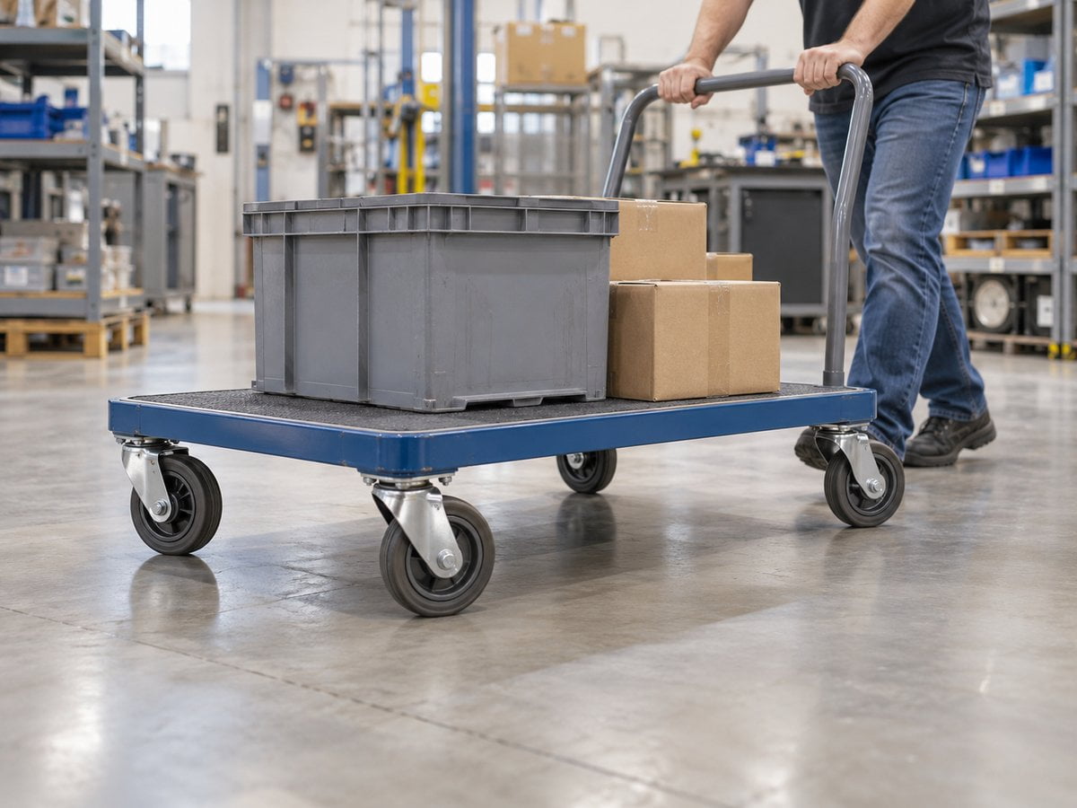
When an operator pushes a cart handle to one side, the cart frame begins to follow a curved path. Each swivel caster responds to the direction of travel at its mounting point: its fork pivots around the vertical swivel axis and the wheel’s rolling plane turns to follow the curve. On a multi-caster cart, the wheels may sit at different angles while travelling around a turn because each caster follows a slightly different local path.
A fixed caster behaves differently. Its wheel can roll, but its fork cannot swivel around a vertical axis. It therefore guides the cart along the wheel’s set rolling direction. A cart using both fixed and swivel casters combines that directional reference with steering flexibility.
What parts on a caster actually move?
The wheel rotates on one axis; the caster fork swivels around another.
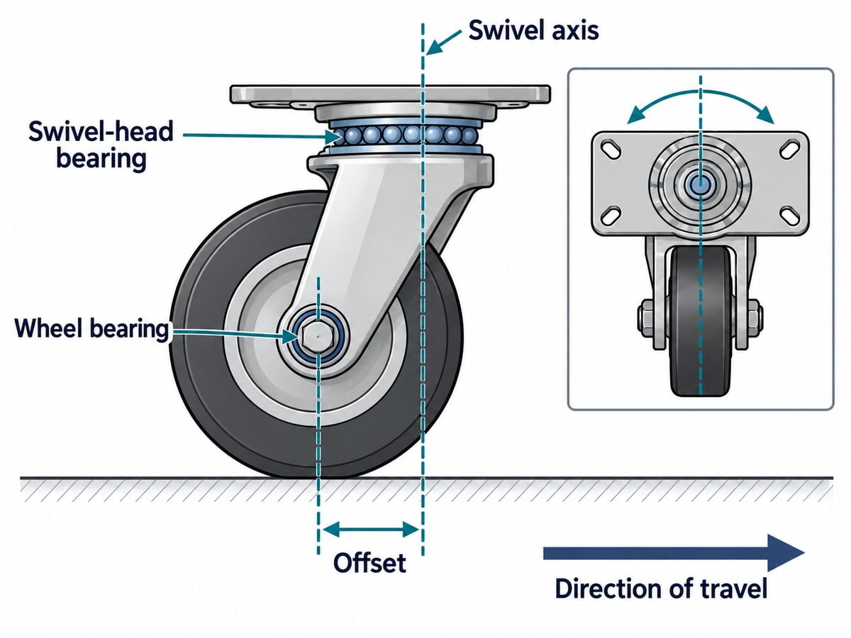
A typical swivel caster has a mounting plate or stem, a swivel head, a fork, a wheel and a wheel axle. The wheel turns around its horizontal axle. The fork and wheel assembly rotate around a vertical axis in the swivel head. These are separate motions and usually involve separate bearing functions.
The wheel bearing supports rotation of the wheel around its axle. The swivel-head bearing supports the caster’s steering rotation between the mounting section and the fork. A cart can roll freely yet still be difficult to steer if the swivel mechanism does not turn smoothly; conversely, a smooth swivel head does not compensate for a wheel that rolls poorly. Blickle’s component definitions distinguish the wheel bearing from the swivel head (swivel bearing). Blickle’s caster component guide
Why does caster offset help a wheel align?
The offset lets the wheel trail behind the swivel axis and follow the direction of motion.
The wheel axle is normally displaced horizontally from the vertical swivel axis. When the cart changes direction, the floor’s reaction at the wheel contact patch acts at a distance from that axis. This produces a turning moment that swings the fork until the wheel is aligned with its travel direction. In ordinary use, the wheel trails behind the pivot rather than remaining directly underneath it.
The geometry also creates a clearance requirement: the caster and wheel need room to sweep as the fork rotates. The required space depends on the caster’s dimensions and mounting position, so a cart frame, brake pedal or nearby structure should not obstruct the swivel path. Blickle describes the offset as supporting free swivel motion and stable rolling when travelling straight. Blickle’s explanation of swivel castors and offset
How does caster layout affect a cart’s turn?
The mix and position of fixed and swivel casters set the balance between steering freedom and straight-line tracking.
| Caster layout | Typical steering behaviour | Design consideration |
|---|---|---|
| Two fixed and two swivel casters | The swivel pair turns while the fixed pair helps define a preferred travel direction | The fixed pair’s position affects how the operator steers and how the cart tracks |
| Four swivel casters | The cart can manoeuvre in more directions and turn within a smaller space | It may feel less directionally stable on some floors or slopes |
These are common layouts, not universal rules. Hammer Caster’s industry guide describes both two-fixed/two-swivel combinations and four-swivel arrangements, noting the greater multidirectional movement of four swivel casters and the potential trade-off in straight-line stability on slopes. The best arrangement depends on the cart’s geometry, load, push or tow method and route. Hammer Caster’s industrial caster guide
What affects how easily an industrial cart turns?
Caster geometry matters, but the whole cart and its route matter too.
Several factors influence the effort and control required to change direction:
- Caster placement: The spacing between casters and their position relative to the handle affect how the cart responds to steering input.
- Load distribution: Unevenly distributed cargo can increase the force on some casters and change how the cart responds in a turn.
- Wheel and swivel bearings: The wheel bearing and swivel-head bearing perform different jobs; smooth rotation at both interfaces supports predictable movement.
- Wheel and floor pairing: Wheel material, diameter, tread and floor condition affect rolling resistance and how readily a wheel follows a curved path.
- Obstacles and transitions: Joints, debris, ramps and uneven surfaces can interrupt rolling and make a turn feel harder.
- Brakes and directional locks: A wheel brake stops wheel rotation. A total-lock design may also prevent the swivel head from turning. A directional lock holds the swivel caster in a selected direction, so the caster behaves more like a fixed wheel while that lock is engaged. Blickle’s brake and directional-lock explanations
For an OEM design, assess turning with the intended load, floor, route and operating mode. A caster arrangement that feels responsive on a smooth factory floor may behave differently on ramps, joints or uneven outdoor surfaces.
How are casters different from guide rollers?
A caster steers over a floor; a guide roller follows a defined rail or track.
A caster assembly lets a cart change its travel direction across a floor because the fork swivels around a vertical axis. A guide roller or bearing roller is usually constrained by a mating rail, profile, cable or track. It may help a cart or carriage stay on a prescribed path, but it does not provide the same free-swivelling steering action as a floor-mounted caster.
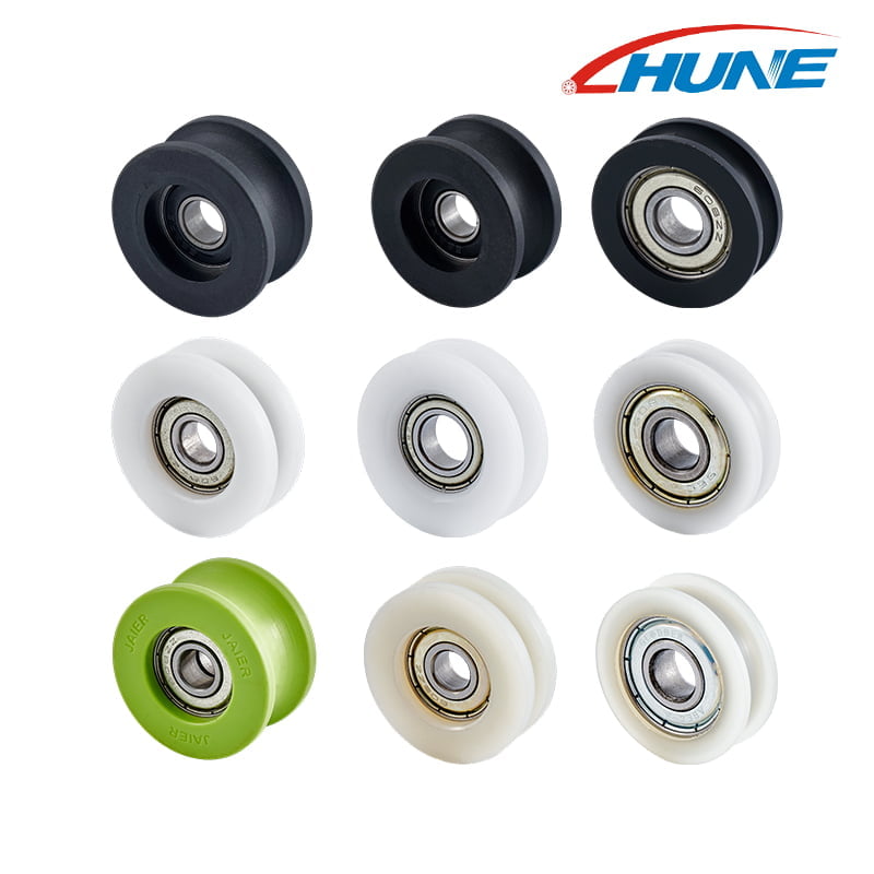
For equipment with a fixed rail or guided transfer path, see HUNE’s bearing rollers with bearings and U-groove bearing rollers for guided rails. The wheel profile, bearing and mating track must be considered together. These products are guide-roller components, not complete caster assemblies. HUNE’s custom bearing-roller materials and manufacturing guide outlines the broader component and assembly considerations.
What should OEM buyers specify?
Describe the cart, its load and its route before selecting a caster or a guided roller.
For a caster supplier, an OEM brief should identify the cart’s unloaded and maximum loaded mass, load distribution, caster mounting points, push or towing method, desired turning behaviour, floor conditions, obstacles, operating speed and duty cycle. It should also state whether the cart needs wheel brakes, total locks or directional locks.
If the design includes a separate guide rail or roller path, send the rail cross-section, roller profile, dimensions, bearing and shaft requirements, tolerances, environment and expected movement cycle. A drawing or physical sample helps the supplier assess the mating geometry and the complete rolling assembly. HUNE’s custom bearing-roller materials and manufacturing information is relevant to those track-guided roller requirements.
Frequently asked questions
Do all industrial carts use swivel casters?
No. Some carts use a combination of fixed and swivel casters to balance directional tracking and steering. Other carts use four swivel casters for greater manoeuvrability, or use wheels and rollers constrained by a guide track.
Why does a swivel caster wheel sit behind its swivel axis?
The offset places the wheel contact point behind the pivot in the direction of travel. When the cart changes direction, the contact force creates a moment around the swivel axis, allowing the fork to turn and the wheel to align with the new path.
Is the caster wheel bearing the same as the swivel-head bearing?
No. The wheel bearing supports wheel rotation around the axle. The swivel-head bearing supports the fork’s rotation around the vertical steering axis.
Can a bearing roller replace a caster?
Not as a direct one-for-one substitute in every design. A caster allows a cart to travel over a floor and swivel to steer. A bearing roller usually runs against a rail or track to support or guide movement along a defined path. The application geometry determines which component is suitable.
Practical recommendation for OEM buyers
Choose the wheel arrangement around the cart’s route and steering method, then verify the complete assembly under the intended load. Specify whether the cart must track straight, turn tightly, move sideways or follow a fixed rail. For a guided-rail design, provide the drawing or sample, track profile, load, speed, duty cycle and environment so the roller, bearing and mating geometry can be evaluated together.
EDITORIAL VERIFICATION RECORD (not part of article body)
- Search intent: informational mechanism explanation with a practical OEM component-selection angle.
- Existing-topic check: no exact duplicate title found in the available article folders. Nearby conveyor, track-guided roller and bearing topics were differentiated from floor-mounted caster steering.
- Business alignment: the article distinguishes HUNE bearing rollers for guided systems from complete floor-mounted caster assemblies; it does not claim HUNE manufactures casters.
- Technical verification: checked caster part names, wheel-bearing versus swivel-head-bearing functions, swivel offset, fixed-caster behaviour, common layouts and brake/lock distinctions against manufacturer material.
- Limitations: no test data, universal load values or search-volume values are asserted. Search volume was unavailable in this research round.
- Sources reviewed: Blickle basic information/definitions; Blickle bracket types; Hammer Caster industrial caster guide (2024 edition); HUNE bearing-roller category, U-groove product and materials/process pages.
- Image notes: image 01 and image 02 are generated illustrations, not product-performance evidence. Image 03 is from the HUNE media library.