Machine guard doors usually move when rollers attached to the door or its carriage travel along a fixed guide rail. The rail establishes the path, the rollers carry and guide the panel, and stops define the ends of travel. A lower guide may control sway, while a latch or interlock handles the closed-position or machine-control function. These jobs should be designed as one door system, but they are not interchangeable: a smooth-running roller does not make a guard safe, and a rail does not replace an interlock. For OEMs, the key is to match the guide geometry and roller assembly to the panel, operating environment and required safety design.
What parts make a sliding machine guard door move?
The door moves as a guided assembly, not as a wheel alone.
A typical manual sliding guard door includes a framed panel, one or more upper guide rails, roller carriages or bearing rollers, a lower guide or stabilizer, travel stops, handles and a closure arrangement. Some designs are top-hung; others support more of the panel near the floor. Powered doors add an actuator and control components, which introduce their own design and safety requirements.
The upper rail and rollers usually establish the primary travel path. Their spacing and mounting position affect how the door hangs and how the panel responds to pushing. A bottom guide may keep the panel from swinging or lifting away from its intended path. Stops prevent the carriage from running off the rail and can help locate the door at its end positions, but they should be designed for the actual moving mass and operation rather than treated as decorative end caps.
A door may also include a latch, guard-locking device or safety interlock. Those components address access and machine-control functions. ISO describes general design and construction requirements for fixed and movable guards in ISO 14120, and notes that interlocking devices are covered separately by ISO 14119. The selected safety architecture must follow the machine risk assessment and applicable requirements.
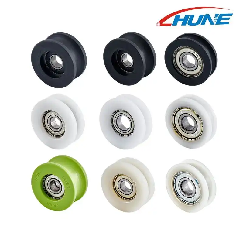
Image placement — after this section: HUNE media-library image showing bearing-integrated roller options.
 The wheel profile and mounting arrangement must match the mating guide and the door structure.
How do rollers and guide rails work together?
The rail controls the path; the roller interface turns sliding contact into rolling movement.
As an operator pushes the handle, force passes from the door frame into the roller carriage. The wheel rotates around its bearing or axle while its running surface follows the rail. This reduces sliding friction at the contact interface and helps the panel move along a defined line.
The exact contact depends on the rail and wheel profile. A flat roller may run on a flat surface; a V-groove roller needs compatible angled rail faces; a U-groove or flanged roller may capture or follow a round rail or defined edge. Profile mismatch can create edge loading, rubbing, noise or unstable tracking even when the bearing itself rotates freely. This is why buyers should send the rail cross-section or sample instead of specifying a wheel by outside diameter alone.
Rollers also see more than the static panel weight. The load path can include the door’s center of gravity, roller spacing, hand force, acceleration and deceleration, frame deflection, impact at stops and rail alignment. Without the specific assembly geometry and operating conditions, a generic capacity number cannot establish whether a roller is suitable.
Image placement — after this section:
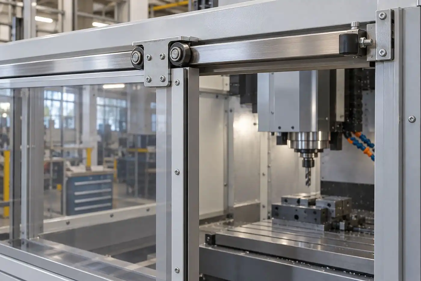
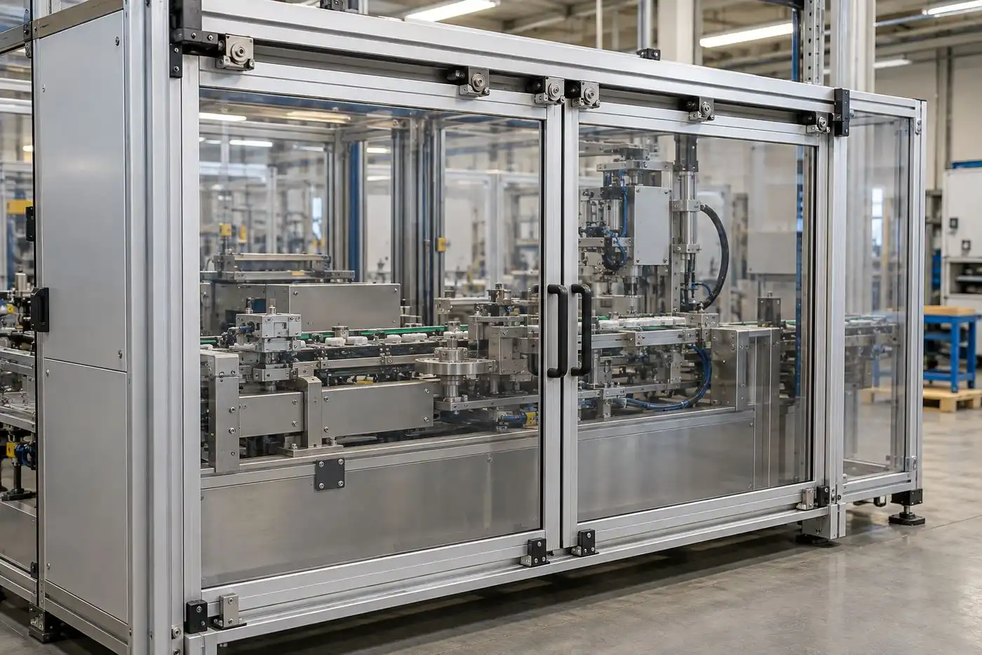 The roller carriage, rail, panel frame and stop should be assessed together.
Why may a machine use both upper and lower guidance?
A second guide can control panel sway without carrying the same function as the upper rollers.
A top-hung arrangement can leave the bottom edge free to swing unless the design includes a lower guide, captured track or equivalent stabilizing feature. A bottom-supported door may still use an upper guide to constrain lateral movement. The exact division of support and guidance depends on the construction; it should be confirmed from the door drawing rather than assumed.
Clearance matters. Too little clearance between a lower guide and its track can cause rubbing as the frame moves or deflects. Too much can permit unwanted sway, misalignment at the latch, or inconsistent positioning at an interlock actuator. The designer should account for the rail alignment, door-frame stiffness, mounting tolerance and expected wear across the full travel.
The guide system must also avoid creating new pinch or shear points. OSHA’s machine-guarding guidance cautions that guards must not introduce hazards between the guard and other machine parts; see OSHA’s Safeguarding Equipment and Protecting Workers guide. That is one reason the door envelope, edges, gaps and adjacent machine structure need to be reviewed as a complete assembly.
Image placement — after this section:
 The lower guide constrains the panel while the upper rail and roller carriages define its main travel path.
What affects smooth, repeatable door movement?
Fit, alignment, contamination and duty cycle often matter as much as bearing selection.
A sliding door may feel rough or track inconsistently when the rail is not straight, the roller profile does not match the track, the door frame is distorted, or multiple carriages are forced to compensate for misalignment. Chips, abrasive dust, coolant and cleaning fluids can also affect a guide mechanism. In one machine-door application, linear-guide manufacturer Franke specifically identifies temperature changes, cooling or cleaning fluids, compressed air and chips as conditions the guidance system must accommodate (Franke machine-door application).
For that reason, specify the environment alongside the dimensions. Bearing shields or seals, corrosion-resistant materials, wipers, wheel polymer and lubricant compatibility may matter depending on exposure. No single closure or wheel material is right for every enclosure.
What should OEMs include in a guide-roller RFQ?
Send the mating geometry and door conditions so the supplier can evaluate the complete interface.
For a custom machine guard door roller or guide-wheel assembly, provide:
- The rail cross-section, dimensions and material, preferably as a drawing or physical sample.
- Roller profile, outside diameter, width, groove angle or radius, flange spacing and other contact dimensions.
- Bearing bore or reference, shaft or stud dimensions, retention method and available mounting space.
- Door-panel mass, roller locations and spacing, travel length, expected operating frequency and whether movement is manual or powered.
- Environmental exposure such as chips, dust, coolant, washdown, temperature and corrosion conditions.
- Required end stops, lower guidance, latch or interlock mounting interfaces, along with sample-approval and inspection requirements.
A supplier can then review whether an existing roller profile is appropriate or whether the wheel, bearing, shaft or bracket needs customization. HUNE’s sliding rollers with bearings include multiple profiles and mounting structures for guided motion applications. For a project that needs the roller and hardware coordinated, see the OEM manufacturing process. The roller supplier can support component fit and repeat production, while guard performance and safety control remain part of the machine builder’s design responsibility.
Frequently asked questions
Do all machine guard doors use rollers on a top rail?
No. Some are top-hung, while other designs support the door from below or use dedicated linear-guide systems. The support and guidance arrangement depends on panel size, enclosure design, available space and operating duty.
Are machine guard door rollers safety devices?
A roller is a motion component. It supports or guides the door, but it does not perform the safety function of an interlock or guard-locking device unless it is part of a specifically designed and validated system.
Why can a sliding guard door bind even when its bearings turn freely?
The cause may be track misalignment, incompatible wheel and rail geometry, frame distortion, excessive side constraint, contamination or uneven load sharing. Evaluate the door, rails and roller positions together.
Should the lower guide carry the door’s weight?
That depends on the door architecture. In some designs it only limits sway; in others, lower components contribute to support. Confirm the intended load path in the assembly drawing and do not infer it from appearance.
What information is most useful for selecting a replacement or custom roller?
A rail section or sample, the roller’s functional dimensions, mounting details, panel conditions and environment are more useful than a photo alone. Include a photo for context, but use a drawing or sample to verify mating geometry.
Practical recommendation
Specify the door system as a set of mating interfaces. Before choosing a roller, confirm how the panel is supported, how the rail constrains it, what the lower guide does, where the stops act and how the guard’s safety function is implemented. Then test the proposed roller and track together under representative operating conditions and approve the sample against the assembly drawing.