

If an OEM buyer asks how to make a sliding barn door, I would not begin with cutting a timber panel or choosing a decorative handle. I would first define the complete sliding system: the panel, hanger plates, bearing rollers, track, mounting structure, anti-jump retention, travel stops and bottom guide. Each part must share a controlled load path and compatible geometry.
The direct answer: make the door as a system. Set the panel mass and travel first, design the track and roller interface around that requirement, control the hanger and guide datums, and validate the assembled door before releasing any component for volume production.
This is an OEM engineering guide rather than a household installation tutorial. It explains what manufacturers and sourcing teams should specify, prototype and approve when developing a repeatable sliding barn door product.
Start With the Product Requirement, Not the Hardware Catalogue
A reliable barn door design begins with the opening, panel and duty profile. The roller can only be selected after those conditions are known.
A catalogue roller may look suitable because its diameter or finish matches the concept. That does not show whether its groove fits the track, whether the axle can transfer the door load, or whether the bracket places the panel at the correct height. I normally define the following requirements before comparing hardware:
- clear opening width and height;
- door panel width, height, thickness and expected mass range;
- required travel and overlap at the closed and open positions;
- indoor, humid, corrosive or outdoor exposure;
- expected operating frequency and target product life;
- acceptable push force, noise and visible movement;
- wall, frame or machine structure available for track mounting;
- exposed, concealed or partially concealed hardware;
- applicable market, project specification and validation standard;
- expected order quantity, annual demand and product revision risk.
The requested appearance still matters, but it follows the functional definition. A slim exposed hanger may suit a light interior panel yet leave too little stiffness or adjustment for a larger product. A concealed trolley may provide a cleaner face but requires a different track section, service access and assembly sequence.
For a first comparison of track and wheel compatibility, our guide to selecting sliding door tracks and rollers explains why the track cross-section should be reviewed before the wheel outside diameter.
Which Parts Make Up the Complete System?
A top-hung barn door needs more than two wheels and a rail. The primary hardware carries vertical load, while secondary hardware controls sway, retention and travel.
| System element | Main function | Interface that must be defined |
|---|---|---|
| Door panel | Closes the opening and transfers forces into the hangers | Thickness, stiffness, mass, top mounting zone, edge condition |
| Hanger plates or trolleys | Connect the panel to the rotating hardware | Hole pattern, fasteners, panel datum, adjustment range |
| Roller, bearing and axle | Support rotation and transfer load to the track | Running profile, bearing seat, axle shoulder, axial clearance |
| Track or rail | Carries and guides the rollers | Cross-section, running surface, straightness, mounting-hole pattern |
| Track spacers and brackets | Transfer the system load into the structure | Stand-off, wall/frame strength, fastener access, alignment |
| Anti-jump retainers | Help keep the rollers engaged with the track | Retention gap, roller envelope, track underside geometry |
| End stops | Define safe travel limits | Stop face, impact path, fastener retention, adjustment |
| Bottom guide | Restrains lateral panel movement | Guide position, slot or panel edge, working clearance |
| Handle or pull | Applies user input | Hand clearance, fastener reinforcement, interference envelope |
| Optional soft close | Controls the final part of travel | Trigger position, available stroke, panel energy, reset behavior |
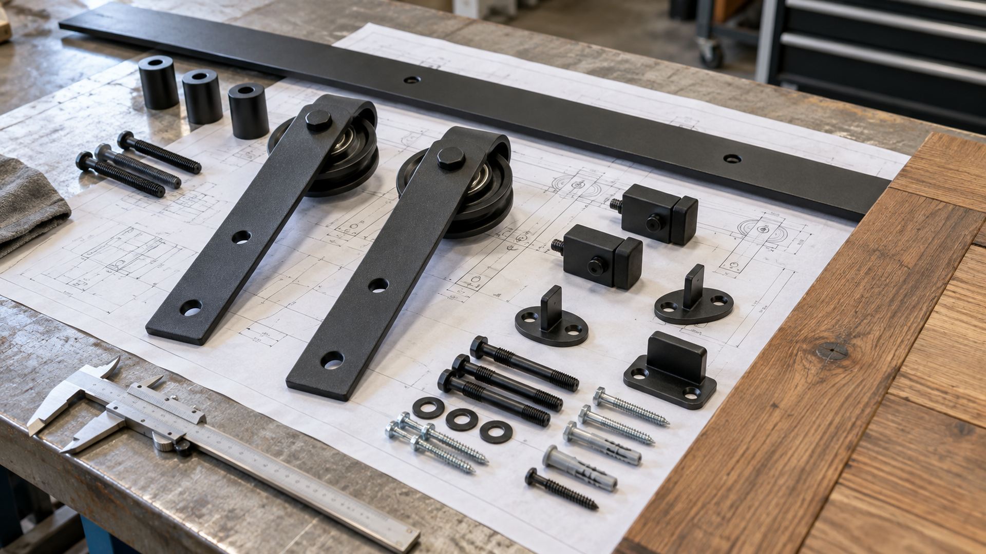
The main load path is:
door panel → hanger connection → hanger plate → axle and bearing → roller running surface → track → mounting bracket or spacer → supporting structure
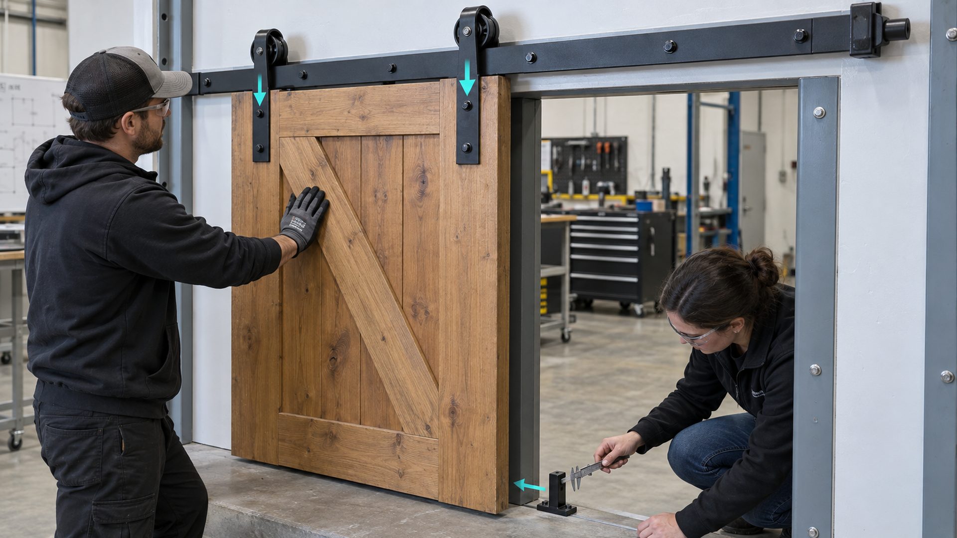
The bottom guide should normally control lateral motion, not carry the panel's main weight in a top-hung architecture. If it begins to carry vertical load because the track sags or the panel drops, the system is no longer working as intended.
How Should the Door Panel Be Designed?
The panel must remain sufficiently flat and stiff for the chosen guide clearances and hanger spacing. A visually attractive panel that twists can still produce a poor sliding system.
Solid wood, engineered wood, framed glass and metal-framed panels behave differently. For a timber product, moisture-related dimensional change deserves attention during design and validation. The USDA Forest Products Laboratory's Wood Handbook documents moisture content and dimensional-change behavior for wood as an engineering material. The practical implication is that a wooden door should not be evaluated only in the condition in which the first sample leaves the workshop.
I normally check:
- whether the top rail or mounting zone can transfer the hanger load without local crushing or splitting;
- whether the panel remains flat enough for the bottom guide throughout its expected environment;
- whether mounting holes leave adequate edge distance and reinforcement;
- whether decorative cross braces actually contribute structure or are cosmetic;
- whether the panel mass and center of gravity remain within the intended hardware envelope;
- whether finishes on both faces may influence moisture response or appearance.
The drawing should identify the panel datum from which hanger height and bottom-guide engagement are measured. If the panel supplier, hardware supplier and assembly factory each use a different reference, accumulated variation appears as unequal wheel loading, rubbing or inconsistent floor clearance.
How Do the Track and Rollers Need to Match?
The functional interface is the roller's actual running profile against the track, not the nominal wheel diameter.
For an exposed flat-track barn door, a grooved or flanged wheel captures the track edge or running band. For an enclosed overhead track, a compact trolley may run inside a formed channel. These architectures should not be mixed casually: their load directions, retention methods, assembly access and contamination behavior differ.
When reviewing a roller-track pair, I focus on these questions:
- Which roller surface actually carries the vertical load?
- Does the groove radius or flat running band contact the intended part of the track?
- Is there enough lateral guidance without forcing the wheel against a flange continuously?
- Can the bearing tolerate the resulting radial load and any unavoidable axial component?
- Does the roller remain captured when the panel is lifted, pushed sideways or stopped abruptly?
- Can dirt, coating buildup or track joints disturb the contact path?
- Does the axle shoulder clamp the correct bearing ring without binding rotation?
A buyer comparing integrated wheel-and-bearing constructions can review HUNE's sliding rollers with bearing as examples of how the outer tread, bearing and mounting feature may be combined. The page is a starting point for architecture comparison; the final choice still depends on the mating track and door geometry.
Steel, Polymer or Polymer-Coated Running Surfaces?
The running material changes noise, wear, impact response, contamination sensitivity and track interaction. It should not be selected by a single slogan.
| Running surface | Useful when | Main checks before approval |
|---|---|---|
| Steel | Compact contact, rigid geometry and a metal-on-metal design are acceptable | Track hardness and finish, noise, corrosion protection, edge loading |
| Engineering polymer | Lower running noise and separation from metal contact are priorities | Exact grade, creep, wear, moisture or temperature exposure, moulded geometry |
| Elastomer or coated wheel | Damping and surface compliance are useful | Bond or retention, compression set, debris pickup, running diameter variation |
Material names such as nylon, POM or PU are not complete specifications. Grade, filler, pigment, recycled content and supplier data can affect performance. I would request the proposed material designation and approve it together with the production process rather than approve only a generic resin family.
Which Functional Dimensions Should the Drawing Control?
Control the dimensions that position the door and create the rolling interface. Tight tolerances on hidden cosmetic surfaces do not compensate for an uncontrolled load path.
The most useful drawing controls usually include:
| Functional feature | Why it matters | Typical inspection approach |
|---|---|---|
| Roller running diameter | Sets travel geometry and hanger height | Diameter measurement at the defined running band |
| Groove width, depth and radius | Determines track contact and lateral guidance | Profile gauge, optical check or section comparison |
| Bearing seat and retention | Controls fit and bearing location | Bore/seat measurement and assembly check |
| Axle diameter, shoulder and thread | Transfers load and locates the bearing rings | Dimensional inspection and torque/retention review |
| Roller-to-hanger offset | Positions the load relative to the plate and panel | Fixture measurement from defined datums |
| Hanger hole pattern | Controls connection to the panel | Coordinate or functional-gauge inspection |
| Track running-surface position | Establishes the door path | Cross-section and installed-datum check |
| Track straightness and joint condition | Influences push force, noise and chatter | Straightedge, fixture or installed run check |
| Panel-to-wall stand-off | Prevents rubbing and provides trim clearance | System-level dimensional stack review |
| Bottom-guide engagement | Controls lateral motion without binding | Installed clearance and full-travel check |
| Stop position | Sets opening, overlap and impact location | Travel measurement on the assembled system |
| Roller runout and concentricity | Affects vibration and periodic force | Indicator or functional rolling fixture |
The exact tolerance depends on the architecture, manufacturing route and required performance. I do not assign a universal number before seeing the stack-up. First identify the door-position datum, track datum and roller contact line; then calculate how variation from each part affects clearance and load sharing.
Track length also comes from the required travel, closed overlap, open parking position and stop allowance. Merely doubling the opening width may be a rough concept rule, but it is not a production drawing.
What Prevents Jumping, Sway and Overtravel?
Safety and control hardware should be designed into the system from the beginning, because the bearing roller alone cannot manage every force direction.
Anti-jump retainers limit upward separation between the hanger and track. End stops absorb or redirect motion at each travel limit. The bottom guide restrains the panel laterally and prevents it from rotating around the top suspension points. Their positions must work together across the complete door travel.
A practical design review should ask:
- Can the panel be lifted enough to disengage the roller from the track?
- Does a stop load enter a strong part of the hanger or panel?
- Can a stop loosen, rotate or slide after repeated impacts?
- Is the bottom guide still engaged at both ends of travel?
- Can the guide bind when the panel bows or the floor is uneven?
- Are fingers exposed to pinch zones near rollers, stops or the closing edge?
- Can the door strike wall trim, handles or adjacent equipment?
The ANSI/BHMA A156.14-2024 overview confirms that sliding and folding door hardware evaluation can include cycle, abuse, durability static load, smoothness, static friction, kinetic friction and finish tests. It also identifies barn sliding systems within the standard's sliding-door types. The overview is useful for planning; a project requiring compliance should use the full standard and the correct product classification.
When Does a Multi-Wheel Hanger Make Sense?
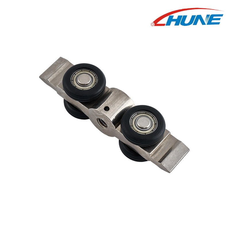
A multi-wheel trolley can distribute contact across several wheels and fit a compact enclosed track, but it creates more interfaces to align and inspect.
An exposed barn door often uses one wheel at each of two hangers. An enclosed overhead track may use two-wheel or four-wheel trolleys so that the load is shared within a channel. The best arrangement depends on track section, panel mass, available envelope and required movement quality.
HUNE's zinc-alloy four-wheel sliding door hanger roller is an example of a compact trolley architecture with bearing-supported wheels and a hanger body. It does not automatically replace an exposed flat-track roller. The track, connector, wheel spacing and panel attachment must be designed around that architecture.
For larger panels or architectures that require a more substantial bracket and axle arrangement, it may also be useful to compare heavy-duty sliding door roller assemblies. “Heavy duty” should still be converted into a defined panel mass, load direction, duty cycle and validation plan before sourcing.
How Should the Hardware Be Manufactured?
The manufacturing route should follow volume, geometry, material and revision risk. The cheapest unit quote can create the highest project cost if tooling is committed before the interfaces are stable.
Typical routes include stamped or laser-cut steel hangers, cast or machined bodies, turned axles, purchased bearings, moulded or machined polymer wheels, surface finishing and final assembly. A single system may combine several processes.
For early prototypes, machined or fabricated parts allow fast dimensional changes. Once the geometry is stable and demand supports tooling, stamping, casting or injection moulding may reduce repeat cost. Hybrid routes are also common: a moulded outer wheel may be assembled over a bearing, while a critical running surface or bore may receive secondary machining if the approved design requires it.
| Project stage | Sensible priority | Main sourcing risk |
|---|---|---|
| Concept sample | Confirm architecture and envelope | Mistaking appearance for validated performance |
| Geometry prototype | Confirm fit, travel and functional datums | Using a prototype process that does not represent production variation |
| Tooling sample | Confirm material, process and critical dimensions | Approving one good sample without checking process stability |
| Pilot production | Confirm assembly, inspection and packaging | Missing accumulated variation across parts and suppliers |
| Repeat production | Control drawings, revisions and inspection | Unapproved material or process substitutions |
Total project cost includes tooling, bearing cost, wheel production, hanger fabrication, finishing, assembly, inspection, scrap, packaging and future engineering changes. I normally compare these costs across the first order and expected annual demand, not only per-piece price.
How Should the Prototype Be Validated?
Validate the installed system with a representative panel. A free-spinning wheel or an attractive hardware sample does not prove door performance.
- Requirement review: confirm the panel, opening, travel, environment, duty profile and target market.
- Geometry prototype: check clearances, mounting access, track engagement, guide position and stop location.
- Material confirmation: verify the proposed wheel, axle, bracket, finish and panel materials against supplier specifications.
- Tooling or production-intent sample: check functional dimensions and assembly behavior from the intended process.
- Installed test: operate a representative door through full travel and observe push force, chatter, noise, sway, rubbing and retention.
- Pilot production: evaluate variation across multiple assemblies and confirm the inspection plan.
- Repeat-production approval: freeze the drawing revision, material specification, approved sample and change-control route.
Testing should reflect the product claim and sales market. If the product will be specified to ANSI/BHMA A156.14 or another standard, obtain the full document and build the formal test plan around its applicable classification. Internal comparison tests can support design decisions, but they should not be presented as certification.
What Should an OEM Buyer Send a Supplier?
A useful enquiry describes the complete application and identifies the functional interfaces. A photo and outside wheel diameter are rarely enough.
Send the following information where available:
- 2D drawing and 3D model with revision level;
- door panel dimensions, construction and mass range;
- track cross-section, material and running-surface detail;
- installed photos or a physical sample if matching an existing system;
- roller running profile, bearing arrangement, axle and hanger geometry;
- door travel, stop positions and bottom-guide layout;
- operating environment, corrosion or finish requirement and cleaning exposure;
- expected frequency of use and validation requirement;
- critical dimensions, datums and inspection method;
- sample quantity, first order, annual volume and project schedule;
- packaging, labeling and traceability requirements;
- target market and any standard or customer specification that applies.
If a drawing is incomplete, mark the uncertain interfaces rather than assigning arbitrary tolerances. A supplier can then review whether an existing roller architecture, a modified axle or bracket, a machined prototype or new tooling is appropriate. HUNE's OEM development process outlines the sequence from requirement review through sample approval and production.
Frequently Asked Questions
What hardware does a sliding barn door system need?
A typical top-hung system needs a track, structural track mounts or spacers, two hanger assemblies with bearing rollers, suitable panel fasteners, anti-jump retainers, travel stops and a bottom guide. A handle and optional soft-close unit may also be required. The exact list depends on whether the rollers run on an exposed flat track or inside an enclosed channel. The wall or frame that carries the track is part of the load path and should be included in the design review.
Should a barn door use steel or polymer rollers?
Neither material is universally better. Steel offers rigid geometry and compact contact but can increase noise and demands careful review of the mating track and corrosion protection. An engineering-polymer running surface can reduce metal-to-metal contact and change noise behavior, but its exact grade, creep, wear and environmental response must be evaluated. I would compare complete wheel-bearing-track samples under the intended panel load rather than approve the material by name alone.
How is sliding barn door track length selected?
Track length comes from the required clear opening, panel overlap when closed, the distance needed to park the panel fully open, hanger spacing and room for both end stops. Wall trim, switches, handles and adjacent equipment can reduce usable travel. The final value should be calculated on the system layout and verified with the stop positions. A simple multiple of the opening width may be useful during concept work, but it should not replace the production drawing.
Can one barn door roller fit different tracks?
Only if the running profile, contact line, lateral clearance, axle position and retention envelope are compatible. Two tracks that look similar from the front may have different thicknesses, edge radii, flange positions or coating buildup. Those differences can shift the contact patch or make the wheel bind. Before approving interchangeability, compare cross-sections and test the roller through the complete travel with representative mounting tolerances.
Build and Source the Door as One System
The practical way to make a sliding barn door for OEM production is to freeze the interfaces before optimizing individual parts. Define the panel mass and stiffness, then establish the track datum, roller contact geometry, hanger connection, retention, stops and bottom guide. Control the dimensions that position these interfaces, and validate a production-intent assembly with the actual door.
HUNE manufactures custom sliding rollers, bearing-supported wheels and related metal hardware for door, furniture, appliance and equipment projects. If you are developing a barn door hardware range, send the panel drawing, track cross-section, load direction, critical dimensions, material and finish requirements, expected quantity and validation target through the HUNE engineering enquiry page. Those details make it possible to judge whether an existing structure, a modified assembly or new tooling is the appropriate next step.


