

Roller drawer slide load capacity is determined by the weakest part of the complete load path: the drawer, moving rail, polymer roller, bearing or bore, axle, fixed rail, fasteners and cabinet structure. Slide length, extension, mounting direction, drawer width, load position, cycle requirement and impact at the stops also change the result. The load rating of one bearing or wheel therefore cannot be used as the rating of the slide pair.
For an OEM buyer, a published capacity is meaningful only when its test conditions match the application. A short side-mounted pair supporting an evenly distributed load on a rigid fixture may perform very differently when installed under a wide drawer, mounted flat, fully extended or exposed to vibration. I would treat the catalogue number as a qualified test result, then confirm deflection, operating force, permanent deformation and durability in the actual drawer system.
What Does a Drawer Slide Load Rating Actually Mean?
A load rating describes performance under stated conditions; it is not a universal property of the slide.
For drawer hardware, the quoted value usually applies to a pair of slides installed in a defined orientation, at a defined slide length and drawer width, with the load distributed in a specified way. It may also be linked to a required number of opening and closing cycles.
The Accuride slide-selection guidance states that its ratings depend on factors including slide length, drawer width, mounting orientation, shock, vibration and installation. It also recommends testing the slide in the intended application because application-specific conditions affect performance.
This distinction matters when comparing quotations. One supplier may report a short-duration static limit, while another reports the load carried through a long cycle test with deflection limits. The larger number is not automatically the stronger design.
An engineering specification should identify at least:
- whether the rating is for one slide or one pair;
- side, bottom-edge or flat mounting orientation;
- nominal slide length and travel;
- drawer width and depth;
- load distribution and center of gravity;
- closed, partly extended or fully extended test position;
- static, dynamic, impact and cycle conditions; and
- the pass/fail criteria after testing.
The current ANSI/BHMA A156.9 Cabinet Hardware overview confirms that cabinet hardware evaluation includes operational, cyclical and strength criteria. Buyers should use the full applicable standard or an agreed OEM method when formal compliance is required.
Which Parts Carry the Load in a Roller Drawer Slide?
The load travels through several interfaces before it reaches the cabinet.
In a typical roller slide, the path is:
contents → drawer bottom and sidewalls → drawer rail → roller tread → bearing or plain bore → axle or rivet → cabinet rail → screws or brackets → cabinet structure
Each part can become the limiting element:
| System element | Primary load-capacity concern | Typical evidence of limitation |
|---|---|---|
| Drawer box | Bottom sag, sidewall bending, joint racking | Drawer changes shape or rails lose parallelism |
| Moving rail | Section bending, local buckling, stop strength | Front edge drops or rail remains bent |
| Roller tread | Contact stress, creep, wear, heat | Flat spot, cracking or increasing travel force |
| Bearing or plain bore | Fatigue, brinelling, seizure, wear | Rough rotation or radial play |
| Axle or rivet | Bending, shear, loosening, hole deformation | Tilted wheel or growing clearance |
| Fixed rail | Bending, twisting, local indentation | Misalignment or permanent set |
| Fasteners and brackets | Pull-out, slip, local panel crushing | Rail moves relative to the cabinet |
| Cabinet structure | Side-panel bowing and mounting-surface movement | Slide spacing changes under load |
This is why changing only the roller can fail to improve the assembly. A larger wheel may carry more contact load, but the existing stamped rail, rivet or cabinet panel may then become the weakest part.
How Do the Roller and Axle Limit Capacity?
The wheel must carry the contact load without excessive deformation, while the axle must keep it aligned.
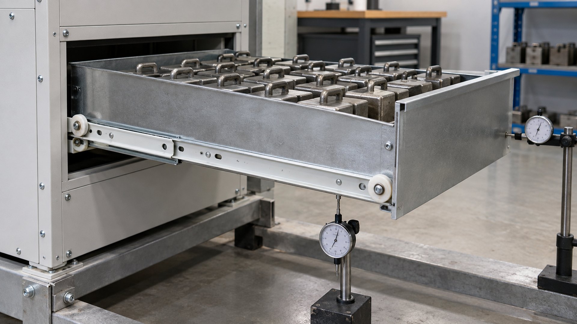 Flat bearing rollers can be customised by wheel diameter, width, material, bore and bearing structure, but the mating rail and axle still control the assembled result.
The roller tread transfers force into a relatively small contact area on the rail. Its diameter, width, crown or flatness, material stiffness, hardness and wall thickness affect the contact condition. A small or narrow wheel can create higher local pressure. A softer polymer may reduce noise and tolerate small track irregularities, but it can also deform more under a sustained load. A harder material may preserve geometry better while transmitting more impact and vibration.
The wheel core can use a plain bore, bushing or rolling bearing. These structures have different friction, wear and load-sharing behavior. For a bearing roller, the bearing’s basic static and dynamic load ratings are relevant to the bearing itself. The NSK explanation of dynamic load ratings and fatigue life describes dynamic rating as a bearing-life concept under defined rotation and reliability conditions. It does not rate the polymer tread, axle, rail or drawer assembly.
Axle diameter, unsupported length, material, heat treatment and retention method affect bending and tilt. A riveted pin that loosens can let the wheel skew even if the bearing remains undamaged. Shoulder squareness and axial clearance also matter: clamping the rotating member or allowing excessive side movement can increase drag and wear.
HUNE’s flat roller wheels with bearings for sliding systems illustrate the component variables available to OEMs. Selection should start from the rail contact, load and duty cycle rather than copying only an outside diameter.
How Does Rail Geometry Affect the Rating?
The rail cross-section often controls system stiffness before the roller reaches its material limit.
A roller slide uses formed steel or aluminium members to support and guide the moving drawer. Section height, material thickness, return flanges, embossments and local reinforcements influence bending and torsional stiffness. Increasing thickness can help, but section shape and unsupported length are equally important.
The rail also forms the running surface. Its width, flatness, edge radius, surface finish and hardness determine how the roller contacts it. A sharp edge or narrow contact band can concentrate stress in the polymer. A rail that twists under load moves the contact toward one side of the wheel and adds lateral force.
Stops deserve separate attention. The steady load during travel may be acceptable, while a forceful opening impact deforms the stop or axle attachment. A soft-close device, detent or damping element changes the force-time history but does not remove the need to validate the end condition.
For a custom design, the roller and rail should be developed together. HUNE supplies custom stamped metal parts for sliding-roller assemblies, allowing wheel contact, rail section, holes and attachment features to be reviewed as one system.
How Do Extension and Load Position Change Capacity?
The same mass creates a larger bending moment as its center of gravity moves farther from the cabinet.
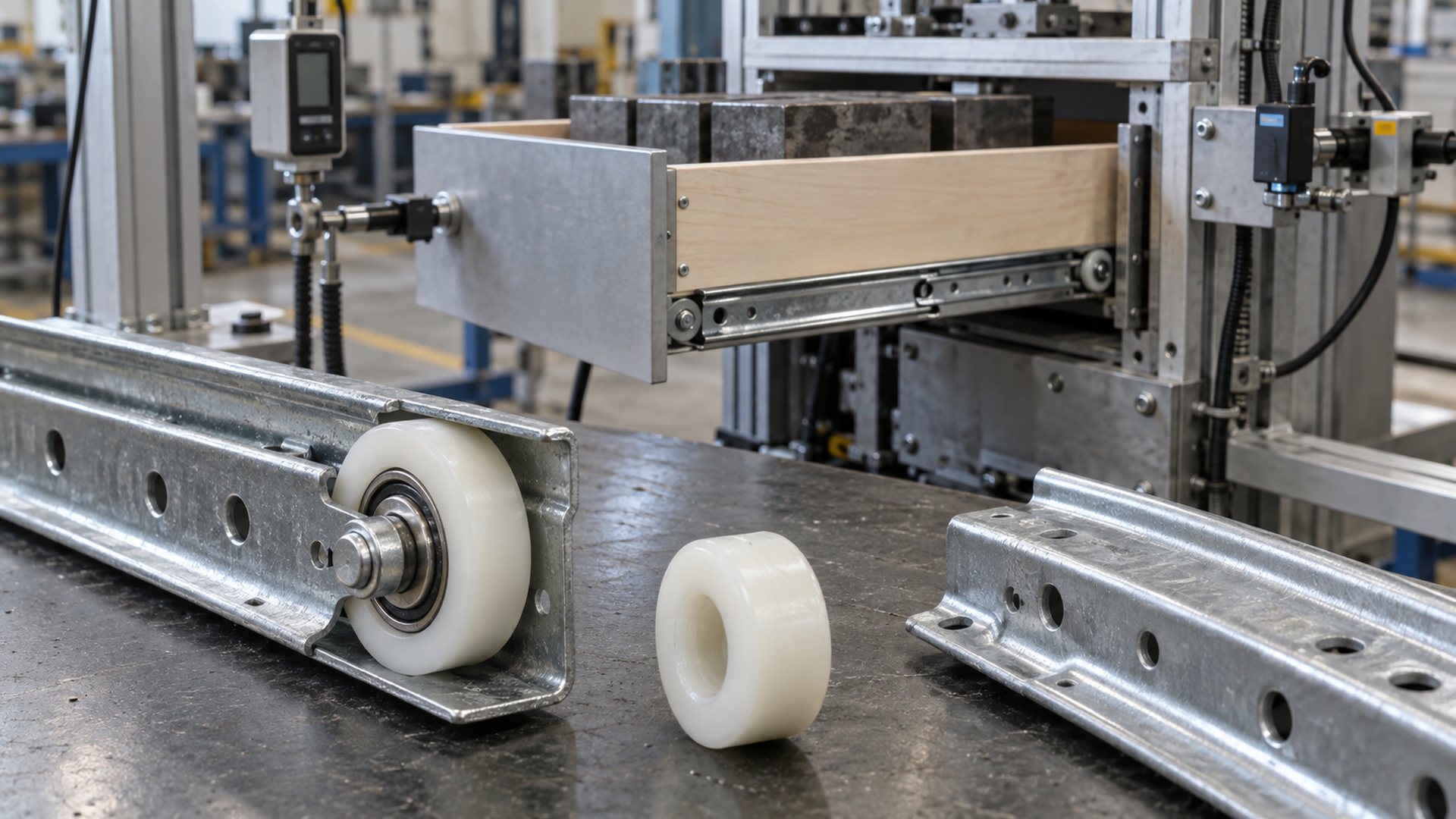 A meaningful load test states the extension, load distribution, drawer dimensions and measurement points.
When a drawer is closed, the cabinet structure supports the load over a compact region. As the drawer extends, the load center moves outward. Rail overlap decreases, the front edge acts through a longer lever arm and bending increases. Full-extension performance is therefore a more demanding condition than closed-position support.
Load position matters as much as total mass. An evenly distributed payload produces a different reaction from a concentrated tool, battery, appliance component or stack of files at the front corner. An offset load can also twist the drawer and cause one slide to carry more than half of the total.
Drawer width adds another effect. A wide drawer gives the user more leverage to pull from one side and makes racking easier. If the drawer box lacks torsional stiffness, the left and right slides do not move together. The result may be higher force or binding before a component reaches its strength limit.
This topic is related to, but different from, our guide on why drawer slides bind under load. Binding focuses on alignment and clearance; capacity evaluation also asks whether the structure survives the required static, dynamic and cycle conditions.
Why Does Mounting Direction Matter?
A slide rated on edge can lose substantial stiffness when mounted flat.
Formed rails are directional structures. A section that resists vertical bending when mounted on the drawer side may be much less stiff when rotated under the drawer. The roller may also contact a different surface or shift laterally in a way the original design did not intend.
Accuride warns that flat mounting can reduce the rating of some models by at least half and requires the specific technical sheet to be checked. That figure should not be copied to every product; the reduction depends on the rail and carriage design. The engineering lesson is that orientation must be part of the rating.
Fastener orientation changes too. Side-mounted screws may work mainly in shear, while another arrangement may introduce withdrawal or prying forces. Thin cabinet panels can crush locally around screws, changing alignment even when the steel slide remains elastic.
If an OEM needs bottom mounting, the supplier should rate and test that exact arrangement. Rotating a side-mount slide in the customer’s assembly is not a reliable substitute for a validated bottom-mount design.
What Is the Difference Between Static, Dynamic and Cycle Capacity?
A slide can survive a static load once and still fail its durability requirement.
These conditions answer different questions:
| Evaluation | Engineering question | Possible failure mode |
|---|---|---|
| Static load | Can the extended assembly support a load for a specified time? | Permanent bend, wheel flat spot, fastener slip |
| Dynamic travel | Can it move the load at the required force and speed? | High friction, roller heat, derailment, instability |
| Cycle durability | Can it repeat the motion for the required life? | Wear, fatigue, loosened rivet, growing clearance |
| Stop impact | Can it tolerate opening or closing shocks? | Bent stop, cracked wheel, pulled fastener |
| Vibration or mobile use | Can it retain load and alignment under repeated external acceleration? | Brinelling, fretting, screw loosening, rail damage |
The ANSI/KCMA A161.1 performance standard treats cabinet structural tests, drawer loading, repeated operation and impact as separate evaluations. This reinforces a useful sourcing principle: capacity and durability should not be reduced to one maximum-weight claim.
For appliance, vehicle, laboratory or industrial equipment drawers, the test profile may need to go beyond residential cabinet methods. The buyer should define acceleration, vibration, temperature, contamination and how often the drawer is operated.
Does a Bearing Roller Automatically Increase Slide Capacity?
A bearing can lower rotational resistance, but it does not automatically strengthen the rail or drawer.
Compared with a plain-bore wheel, a suitable rolling bearing can reduce friction at the wheel-to-axle interface and control radial play. This may improve travel force and wear life under repeated motion. It can be valuable when the drawer is operated frequently or when low and consistent force is required.
However, the slide capacity may still be limited by polymer tread deformation, axle bending, rail deflection or fastener pull-out. A bearing with a high catalogue load rating cannot prevent a thin rail from bending. A larger bearing may even require a larger wheel or different rail section, changing the complete geometry.
The correct comparison uses the same drawer, rail, axle, load, extension and cycle profile. Our article on how bearings reduce friction explains why lubrication, seals, fits and external rolling contact still influence the final force.
How Do Material and Environment Affect Capacity?
Temperature, moisture, chemicals and time can change the properties that supported the original rating.
Polymer wheels may creep under sustained load. Some materials absorb moisture and change dimension or stiffness. Lubricants can thicken at low temperature or migrate at higher temperature. Steel rails and bearings can corrode in humid, washdown or chemical environments, increasing roughness and reducing section strength over time.
Material selection should therefore cover:
- continuous and peak temperature;
- duration of sustained load;
- humidity and water exposure;
- dust, fibres or abrasive particles;
- cleaning chemicals, oils and solvents;
- UV exposure if applicable;
- required noise and rolling-force level; and
- regulations for food, medical or electrical equipment.
POM, nylon, polyurethane and other engineering materials offer different balances of stiffness, damping, wear and environmental resistance. HUNE’s materials and process overview provides a starting point for matching injection molding, overmolding or machining to the application.
Nominally identical slides can carry unequal reactions when the drawer or cabinet is not rigid and square.
The common assumption that each side carries exactly half of the mass is only a starting point. An offset payload, warped drawer, unequal mounting height, rail twist or cabinet deflection can shift the load. At some positions, one roller may briefly carry a much larger share.
This affects component sizing and test fixtures. A perfectly rigid and symmetrical laboratory rig may hide load-sharing problems that appear in the production cabinet. The OEM should include realistic panel thicknesses, fasteners and drawer joints in validation.
Wheel diameter variation and axle position can also affect sharing. If one roller sits slightly higher, it may contact first and attract load. Critical height dimensions should be measured from the mounting datum to the functional running surface, not only as separate component dimensions.
Which Dimensions Should the OEM Drawing Control?
Control the geometry that establishes contact, alignment and load transfer.
| Drawing characteristic | Why it matters | Recommended definition |
|---|---|---|
| Roller outside diameter and width | Sets contact geometry and installed height | Material and inspection condition |
| Tread profile and runout | Controls guidance, force variation and load concentration | Relative to bore or bearing axis |
| Bore or bearing fit | Controls play, retention and ring distortion | Limits plus fit intent |
| Axle diameter and unsupported length | Controls bending and wheel tilt | Include material and retention method |
| Rail running-surface width and profile | Controls contact band and lateral guidance | Reference to mounting datums |
| Rail section height and thickness | Controls bending and torsion | Include material and temper |
| Roller-axis location | Controls drawer height and load sharing | From functional mounting datum |
| Rail straightness and parallelism | Controls smooth travel under load | Installed or free-state condition |
| Mounting-hole position | Transfers rail accuracy into the cabinet | Datum scheme and fastener type |
| Stop geometry | Controls impact and maximum travel | Test load and approach speed |
A blanket tight tolerance on every dimension is expensive and may not control the functional stack. The supplier and OEM should agree which characteristics influence installed height, roller contact and rail overlap, then connect those characteristics to inspection methods.
How Should an OEM Validate a Roller Drawer Slide?
Validation should test the assembled drawer through its real load and motion profile.
 Component inspection and complete-system cycling answer different questions and should both be included.
A practical validation plan progresses through four levels:
- Component inspection: verify roller dimensions, material, bearing or bore condition, axle geometry, rail section and surface finish.
- Slide-pair bench test: measure travel force, vertical and lateral deflection, stop function and permanent set at defined extensions and loads.
- Cycle and impact test: operate the slide through the required travel and cycle count, including representative opening and closing conditions.
- Product-level test: repeat critical checks in the real drawer and cabinet, with production fasteners, realistic load position and environmental exposure.
Record more than pass or fail. Useful outputs include starting and running force, force variation across travel, front-edge deflection, lateral play, permanent deformation, roller wear, axle looseness, noise and any change after cycling.
The acceptance method must define the measurement point and fixture. “Maximum deflection” is incomplete unless the drawing states where the indicator contacts the drawer, how far it is extended and where the payload is placed.
HUNE’s OEM development process supports drawing review, material and tooling decisions, samples and production control. A representative track or complete slide sample is especially useful when only the roller and axle assembly will be custom-made.
What Should a Buyer Send the Supplier?
A complete application brief is more useful than asking for a wheel that carries a stated weight.
Send:
- complete drawer and cabinet drawings or 3D models;
- total moving mass, payload and load-center range;
- drawer width, depth, slide length and required travel;
- mounting orientation and available installation space;
- number and arrangement of rollers;
- rail material, section, hardness, surface finish and mating profile;
- axle or rivet dimensions, material and retention method;
- operating speed, cycle target and duty pattern;
- expected stop impacts, shock and vibration;
- allowable travel force, deflection, play and noise;
- temperature, humidity, dust and chemical exposure;
- applicable standard or in-house test method;
- prototype and annual quantities; and
- inspection reports or traceability requirements.
If the buyer needs only a custom roller, HUNE still needs the mating rail, axle and system conditions. Without those interfaces, a component-level load statement can be misleading.
Frequently Asked Questions
Is the drawer slide load rating for one slide or a pair?
It depends on the manufacturer, but drawer-slide ratings commonly apply to a pair under specified mounting and test conditions. Never assume. Confirm the quantity, slide length, drawer width, mounting orientation, extension and cycle criteria in the technical sheet.
Does a larger roller always increase drawer slide capacity?
No. A larger diameter or wider tread may improve contact conditions, but the axle, rail section, fasteners or cabinet can still limit the assembly. It can also require a different rail profile and installed-height stack. Validate the complete slide rather than the wheel alone.
Why is a slide’s flat-mount capacity lower than its side-mount rating?
Rotating the rail changes the bending axis of its formed cross-section and may change the roller contact and fastener loading. The amount of reduction is design-specific, so use only the manufacturer’s flat-mount rating or test the proposed orientation.
Should the OEM use static capacity or dynamic capacity?
Both may be necessary. Static testing checks support and permanent deformation at a defined condition. Dynamic and cycle testing checks travel force, wear, fatigue and repeated operation. Impact and vibration require separate consideration when they occur in service.
Discuss Your OEM Roller Slide with HUNE
HUNE manufactures custom plastic-coated bearing rollers, plain-bore guide wheels, axles and stamped hardware for furniture, appliances, storage systems and industrial equipment. We review the roller, bearing or bushing, axle, rail, bracket and cabinet interface as one load path.
Send the assembly drawing, load position, slide travel, rail profile, mounting orientation, environment, cycle requirement and annual quantity. Our engineers can then assess wheel material, bearing structure, axle design, functional dimensions and a suitable validation plan. Contact HUNE for an OEM roller-slide review and quotation.
The practical recommendation is to buy against a defined system test, not an isolated wheel or bearing number. Specify how the slide is mounted, loaded, extended and cycled, then confirm that the complete production drawer meets the required force, deflection and durability limits.


