Should you machine a POM roller from bar stock, mould it to its final shape, or mould a near-net blank and finish the critical surfaces by turning? Should you pay for tooling before the track fit has been proven? Can a low prototype price still lead to a stable mass-production part?
I hear these questions whenever an OEM has a drawing but has not fixed the annual demand, functional tolerances or final groove.
I use full machining when the design is still changing or demand is low. I use direct injection moulding when the design and volume are stable. I use moulding plus secondary machining when the main body can be moulded efficiently but the groove, running diameter or face needs tighter control.
All three routes can produce a usable roller. They do not create the same material condition, unit cost, dimensional capability or production risk. Quantity matters, but I first check the running interface, bearing structure and dimensions that control movement.
The choice also depends on how clearly the application requirements have been defined. A roller that fits a drawing may still perform poorly if the mating track, load direction, bearing arrangement or permitted movement has not been considered together. For this reason, I compare the process routes against the complete operating condition rather than judging them by unit price alone.
In this article, I explain how I compare machining, direct injection moulding and moulding with secondary machining for equipment makers, hardware manufacturers, importers and OEM purchasing teams. I focus on commercial production decisions rather than DIY manufacture.
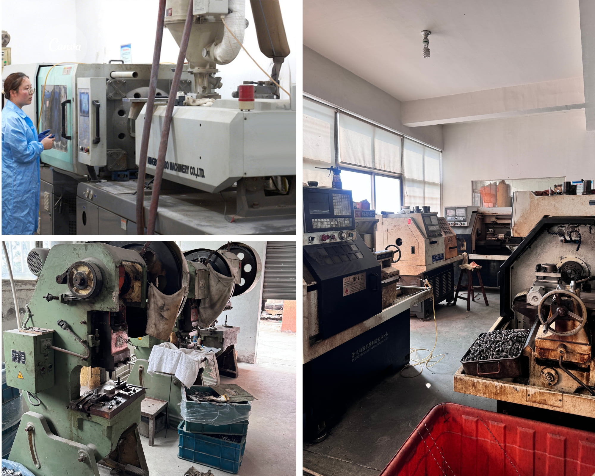
Which Production Route Can Be Used for a POM Roller?
The right route depends on design stability, functional tolerance, material, order volume and the cost of future changes.
I normally assess three routes.
| Production route | How I make the roller | Where I usually consider it | Main commercial limitation |
|---|---|---|---|
| Machining from stock | I turn or mill the complete wheel from POM rod or plate | Prototype, low volume, changing geometry or a large part without justified tooling | Higher unit cost, material waste and slower output |
| Direct injection moulding | I mould the functional profile and hub close to final dimensions | Stable design, repeat demand and geometry suited to mould release | Tooling investment and moulding shrinkage |
| Moulding plus secondary machining | I mould the main body and machine the running diameter, groove or face | Medium or high volume with one or two precision running surfaces | Extra operation, fixture control and machining allowance |
I do not treat this table as an automatic selection rule. A simple wheel at high volume may still need finish turning if its track interface has a narrow tolerance. A complex low-volume part may still justify a small mould if machining wastes too much material.
I also separate the wheel body from the complete assembly. The bearing seat, bearing closure, axle, spacer and bracket can determine performance even when the plastic profile is correct.
Why Should Buyers Define the Running Interface First?
The running interface shows which dimensions affect movement and which dimensions can accept normal production variation.
I first ask where the roller actually contacts the track, rail, cable or mating surface. Buyers often mark the outside diameter as critical while the effective running diameter lies inside a U, V, R or H groove.
I request the mating profile because a nominal groove width does not fully define contact. I need to understand:
- The track or line cross-section
- The intended contact band
- The permitted side clearance
- The direction of radial and axial load
- The entry and exit angle
- The number and spacing of wheels
- The acceptable movement, noise and wear
- The dimensional range of the mating component
I then classify dimensions by function.
| Dimension group | My question | Why the process route matters |
|---|---|---|
| Running profile | Which surface carries and guides the load? | Machining can correct a moulded profile, but it cannot add missing wall thickness |
| Bearing seat | How is the bearing retained without restricting it? | Moulding, overmoulding and press fitting create different stress conditions |
| Axial faces | Which face locates the wheel in the bracket? | Mould draft or flash may affect the installed clearance |
| Overall envelope | Which nearby parts can interfere? | A non-functional cosmetic dimension may accept a wider moulding tolerance |
| Concentric relationship | Which datum controls run-out? | I must hold the wheel from a relevant datum during machining and inspection |
| Groove edges | Can an edge damage the rail, rope or cable? | A machined edge may need a specified radius or deburring method |
I prefer to spend tolerance only where the mechanism needs it. A drawing that assigns a narrow tolerance to every surface can make all three routes more expensive without improving movement.
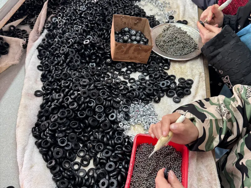
When Does a Machined POM Roller Make Sense?
A machined POM roller usually suits functional prototypes, low-volume orders and projects with a profile that may still change.
I usually consider full machining when the buyer needs prototypes quickly, expects low demand or has not frozen the geometry. It allows me to change a diameter or groove without modifying an injection mould.
I find this route useful for:
- Engineering samples used to verify an installation envelope
- Low-volume non-standard machinery
- Several similar groove variants with uncertain demand
- Large wheels for which early tooling cannot yet be justified
- Replacement parts where the original drawing is incomplete
- Trials that compare two or more contact profiles
I still explain several limits.
First, machined bar stock and injection-moulded material do not have identical manufacturing histories. A successful machined prototype confirms geometry more strongly than it confirms the behaviour of a future moulded part.
Second, machining creates tool marks, burr risk and material waste. A deep, narrow groove can restrict tool access. A thin flange can deflect or chip during cutting. I need a stable holding method that does not distort the bearing seat.
Third, a low prototype quantity can hide repeatability issues. I may make ten carefully inspected parts, but a future production route needs a defined fixture, tool-change rule and inspection frequency.
I therefore use machined prototypes to answer specific questions. I do not use them as automatic proof that an injection-moulded production part will behave identically.
When Does Direct Injection Moulding Make Sense?
Direct injection moulding usually suits a stable design, repeat demand and functional dimensions that can stay within an approved moulded range.
I prefer direct moulding when the design is stable, demand can justify tooling and the functional tolerances are compatible with the material and geometry.
Injection moulding can integrate ribs, flanges, bearing-retention features and non-circular details that would be inefficient to machine. It can also reduce unit labour and material waste at repeat volume.
I review the following points before recommending this route:
- Wall thickness and changes in section
- Gate position and material flow
- Shrinkage around the bearing or insert
- Draft and mould-release direction
- Weld lines near loaded features
- Cooling balance
- Sink-mark risk
- Cavity-to-cavity variation
- Whether the bearing is overmoulded or inserted later
- Whether the final profile can be inspected with a practical gauge
I do not promise that a nominal CAD dimension will emerge from the mould without process allowance. I use trial parts to establish the actual result. If a running dimension must be adjusted, I may modify the tooling or move that surface to a secondary operation.
Direct moulding is less suitable when the buyer expects frequent profile changes, has very low uncertain volume or needs a narrow functional tolerance that moulding alone cannot hold reliably.
I also avoid forcing thick sections into a design merely to simplify the external shape. Thick plastic around a hub can cool slowly and create sink marks or internal stress.
When Does Moulding Plus Secondary Machining Make Sense?
The hybrid route suits a moulded main body with one or two running surfaces that need closer dimensional control.
I often see the hybrid route as a practical production method rather than a correction for a poor mould. I deliberately mould material allowance onto the surfaces that I plan to finish.
The mould creates the main shape efficiently. Turning then controls the running diameter, groove width, groove depth, face or concentric relationship. This method can be useful when one moulded blank supports several closely related variants.
| Hybrid-route decision | When I see value | What I must control |
|---|---|---|
| Finish the outside diameter | The track needs a stable running height | Machining datum, run-out and remaining wall |
| Cut the groove after moulding | Several groove sizes share one body | Tool profile, depth, edge radius and chip removal |
| Face one side | Bracket clearance is functional | Axial datum and final bearing position |
| Machine both faces | Width and centring are tightly linked | Symmetry, holding pressure and cycle time |
| Use one blank for variants | Demand per groove is uncertain | Variant identification and drawing control |
| Correct a small moulded allowance | The actual mould result needs calibration | Approved machining limit, not uncontrolled rework |
I do not recommend secondary machining when it leaves an unsafe flange, exposes reinforcing fibres on a sensitive contact surface or breaks a designed sealing feature.
I also calculate the extra handling, tool wear and inspection cost. A hybrid route can reduce mould complexity but still cost more per part than direct moulding.
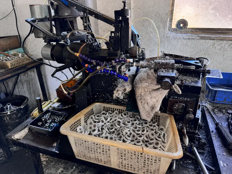
How Do Material Assumptions Change the Result?
The exact POM grade matters because filler, pigment and recycled content can change weight, shrinkage, wear and machining behaviour.
I require an exact material direction because “POM” alone does not define density, filler, shrinkage, wear or machining behaviour. Unfilled POM, glass-fibre-filled POM and mineral-modified compounds can behave differently.
I learned this clearly in a documented custom project. A customer sent us a reference sample and described the outside material as POM with 30% glass fibre. I produced to that stated direction, but the new sample was more than 100 g lighter than the reference.
I sent both materials for testing. The test indicated that the original sample contained POM with approximately 18% glass fibre and mineral filler.
This was not a machining-versus-moulding customer project, and I do not present it as one. I use it here because it exposes a process-selection risk: if I identify a compound only by appearance or an uncertain legacy description, my predicted shrinkage, mass, cutting behaviour and finished dimensions may be wrong.
From my perspective, this case creates four purchasing lessons:
- I should confirm an exact grade when the grade is known.
- I should test an unidentified reference material when weight or performance cannot be reconciled.
- I should approve production material together with the process route.
- I should not assume that a machined sample from one POM grade represents a moulded part in another grade.
I also ask whether recycled content, pigment or filler substitution is permitted. A commercial quotation is incomplete if two suppliers price different compounds under the same generic material name.
What Did a Real U-Groove Project Teach Me?
The project showed that an existing mould is useful only when the blank leaves enough material for the final groove and wall thickness.
In a confirmed customer project, I reviewed a U-groove roller with a required groove width of 5 mm. The available structure was close to the requested dimensions, but the groove needed controlled secondary turning. I planned to machine the groove to 5 mm after moulding.
I did not treat the nominal moulded shape as the final acceptance condition. I treated the machined groove as the functional feature and needed enough plastic allowance around it. This allowed the project to use a close existing structure while controlling the track-related dimension.
The project taught me to separate three questions:
- Does the existing mould provide enough material for the final groove?
- Can I hold the wheel from a datum that keeps the groove concentric with the bearing?
- Does machining still leave enough wall and edge strength for the actual load?
I also recognise the boundary of this example. The method works only when the existing body, bearing arrangement and remaining geometry suit the installation.
I would recommend a new mould if the track geometry, mounting position or required load differed substantially from the available structure.
This case is more useful to a buyer than a general claim that secondary machining is “accurate”. The buyer needs to see the machining allowance, datum, final inspection method and limitation.
How Should Buyers Compare the Real Project Cost?
Buyers should compare tooling, unit conversion, material waste, inspection and future design changes across realistic demand levels.
I compare total project cost over a realistic demand range. I include tooling, material utilisation, machine time, inspection, expected scrap, packaging and engineering changes.
| Cost factor | Full machining | Direct moulding | Moulding plus machining |
|---|---|---|---|
| Initial tooling | Usually low | Highest | Medium to high |
| Unit conversion cost | Usually highest | Usually lowest at stable volume | Between the other routes |
| Material waste | High | Low | Moderate |
| Geometry changes | Relatively easy | Tool modification may be needed | Some machined features can change easily |
| Complex integrated features | Expensive or impossible | Strong capability | Strong for moulded body, limited by finishing access |
| Precision on selected running surfaces | Good with a controlled setup | Depends on moulding capability | Good when the surface is intentionally finished |
| Scale-up risk | Machining capacity and tool life | Tool and process validation | Both moulding and machining must remain controlled |
I ask the buyer for prototype quantity, first order, annual forecast and expected product life. I do not need a perfect forecast, but I need a reasonable range.
I also discuss design stability. A mould can appear cheaper at 20,000 pieces, but it may be premature if the track drawing will change after the first equipment trial. Conversely, machining every production part can become expensive when the design and demand are already stable.
I recommend comparing at least three commercial scenarios: prototype, first production order and expected annual demand. I state which cost includes the bearing, axle, bracket, secondary operation and inspection.
What Should the Drawing Control for Each Route?
The drawing should show which surfaces are moulded, which surfaces are machined and which dimensions control the roller’s function.
I prepare the drawing around function and process. I avoid leaving the production method hidden when it affects acceptance.
For a fully machined wheel, I identify stock material, datum surfaces, tool-access limits, finish, edge treatment and inspection after machining.
For a directly moulded wheel, I identify moulded tolerances, permissible parting line, gate restrictions, material grade, conditioning state and any dimensions established after stabilisation.
For a hybrid wheel, I distinguish moulded dimensions from finished dimensions. I state machining allowance and the datum used during finishing.
| Drawing item | My recommended control |
|---|---|
| Material | Exact resin grade, filler, colour and substitution rule |
| Functional profile | Section dimensions tied to the mating component |
| Running diameter | Measurement method and reference condition |
| Groove | Width, depth or radius plus edge requirement |
| Bearing seat | Size, retention method and inspection stage |
| Concentricity/run-out | Functional datum and assembled test method |
| Surface | Moulded or machined condition and unacceptable defects |
| Process note | Machined, moulded or moulded-and-finished route |
| Revision | Approved geometry and change authorisation |
| Sample status | Prototype, tooling sample, pilot lot or production standard |
I retain an approved sample when practical, but I do not use a sample to replace a controlled drawing. A physical sample helps both sides compare appearance and fit; the drawing shows which characteristics matter and how a future change should be judged.
How Should Buyers Approve the Route Before Mass Production?
Buyers should approve production-representative samples in the real track, bracket or equipment assembly.
I use staged approval because each route answers different questions.
How Do I Approve a Machined Prototype?
I first inspect the critical dimensions and install the prototype in the real track, bracket or mechanism. I record fit, movement, noise, marking and wear.
I state that the prototype material and process may differ from planned mass production.
How Do I Approve a Mould Trial?
I inspect parts from the actual mould and agreed material. I check different cavities where relevant. I review shrinkage, sink, flash, bearing rotation, run-out and functional fit.
I do not approve only the best hand-selected part.
How Do I Approve a Hybrid Process?
I inspect the blank before machining and the finished roller afterwards. I verify that the fixture references the correct datum and that tool wear does not gradually change the groove.
I also inspect chips, burrs and exposed filler.
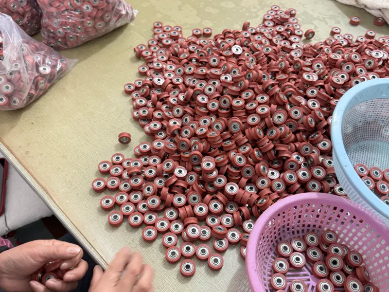
| Approval stage | What I want to learn | Release decision |
|---|---|---|
| Requirement review | Is the contact and load path understood? | Can I choose a process direction? |
| Geometry prototype | Does the profile fit and move correctly? | Can I freeze the functional dimensions? |
| Material confirmation | Does the exact compound meet the requirement? | Can I approve the production grade? |
| Tooling or process sample | Does the intended process reproduce the design? | Can I enter a pilot lot? |
| Pilot production | Do normal operators, cavities and tools remain consistent? | Can I release repeat production? |
| Installed endurance check | Does the complete assembly meet the buyer’s duty? | Can the equipment maker approve the component? |
I ask the equipment manufacturer to set the load, cycles, environment and acceptance criteria. I can manufacture and inspect the roller, but I cannot infer the safety or life requirement of the complete machine.
Which Route Should an OEM Choose?
Choose the route that controls the functional surfaces at the project’s current design stage and expected demand.
I choose full machining when demand is low, the profile is changing or the buyer needs geometry prototypes before tooling.
I choose direct moulding when the design is stable, volume supports the investment and moulded tolerances suit the function.
I choose moulding plus secondary machining when an efficient blank can carry most features but the POM roller needs one or two tightly controlled running surfaces.
I do not decide from quantity alone. I review the track or mating profile, functional tolerance, material grade, bearing arrangement, annual demand and cost of a future design change. I also make the process visible on the drawing and approve production-representative samples.
Buyers can review our sliding rollers with bearing to identify possible starting structures.
They can also review our OEM and ODM development process when a project may need a new mould, secondary machining, an axle or a complete bracket assembly.
If you are comparing these three routes, you can send us the wheel drawing, mating track or cable profile, load direction, critical tolerances, material requirement and demand range.
I can review which dimensions an existing structure may already cover, which surfaces may need finishing and where new tooling would provide better production control. I will state my assumptions so your team can compare the routes on the same basis.