A v groove roller in an aluminium-extrusion motion system does more than carry a moving plate. Its two running faces locate the carriage against the rail, while the bearings, spacers, bolts and mounting plate control how freely and accurately the carriage moves.
This arrangement appears in 3D printers, laser engravers, desktop routers, inspection fixtures and other light automation equipment. These applications may use visually similar wheels, but they do not impose the same load, speed, accuracy or duty cycle.
At HUNE, Zhejiang Huaneng Micro Bearing Co., Ltd., we manufacture plastic-coated bearings, injection-moulded wheels and customised roller assemblies. When an equipment manufacturer asks us to quote a V wheel, the outside diameter is only the starting point. We also need the rail profile, wheel contact geometry, bearing arrangement, spacer stack, mounting-plate dimensions and acceptance method.
This guide helps OEM procurement and engineering teams define those interfaces before they compare samples, approve a mould or release a repeat order. It discusses light motion and guidance systems. It does not rate a wheel for safety-critical machinery, personnel transport or unsupported heavy loads.
Where Does a V Groove Roller Work in an Aluminium-Extrusion System?
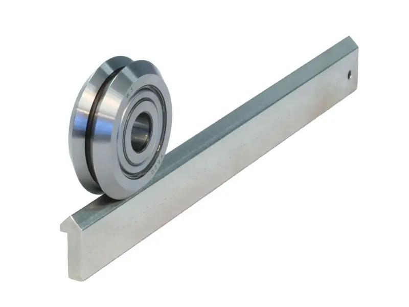
V wheels are often used where a compact carriage must run along the shaped edge of an aluminium profile. The wheel and rail form an external guidance interface. The arrangement is accessible, easy to inspect and suitable for many light mechanisms when the complete system is designed correctly.
Typical engineering applications include:
- X- and Y-axis carriages in desktop 3D printers
- Gantries in laser engraving machines
- Light-duty axes in desktop CNC or drawing machines
- Camera, sensor or inspection carriages
- Adjustable stops in small production fixtures
- Pick-and-place prototypes with moderate motion demands
- Sliding panels or guards in non-safety-critical equipment
- Teaching equipment and development platforms
The wheel does not determine the machine capability by itself. Frame stiffness, rail straightness, plate thickness, belt or screw drive, wheel spacing and applied moment all affect the result.
| Application group | Motion priority | Main wheel-related risk | Information to confirm |
|---|---|---|---|
| 3D printer carriage | Low mass and repeatable movement | Flat spots, play or excess drag | Carriage mass, acceleration and rail profile |
| Laser engraver gantry | Smooth travel over a longer axis | Rail alignment and uneven preload | Span, drive position and wheel spacing |
| Desktop CNC axis | Higher cutting reaction than a printer | Deflection and local wheel loading | Cutting forces, moment load and duty cycle |
| Inspection fixture | Consistent position and low play | Tolerance stack between wheel sets | Datum scheme and allowable carriage movement |
| Sliding equipment panel | Quiet guidance and serviceability | Contamination and wheel access | Orientation, cleaning and replacement method |
A plastic V wheel can be a practical guide component. It should not be presented as a universal substitute for a profiled linear rail. A buyer should compare stiffness, accuracy, contamination, maintenance and life requirements at the system level.
What Must Match Between the Wheel and the Extrusion?
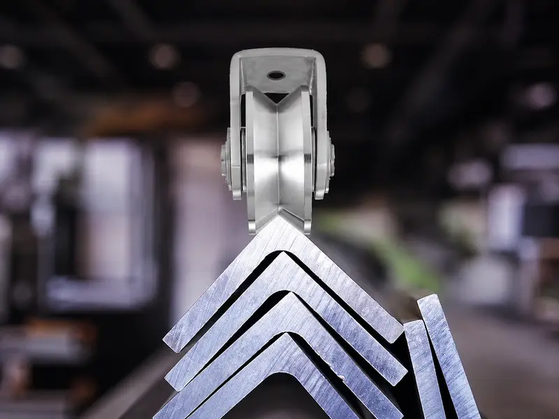
The wheel does not run on the theoretical tip of its V. It contacts two angled faces on the rail. The location and width of those contact bands depend on both profiles.
The buyer should provide the actual extrusion cross-section or a controlled drawing. A trade name such as “V-slot profile” may not define every dimension, tolerance or surface condition across different suppliers.
Included Angle
The angle between the two wheel faces should be compatible with the rail faces. A visible V shape is not enough.
If the angle relationship is wrong, the wheel may:
- Contact near the sharp edge of the rail
- Contact near the wheel’s outer lips
- Rock between two unstable contact positions
- Develop a narrow polished band
- Create higher rolling resistance
- Wear unevenly across a wheel set
The drawing should define the relevant profile angle and its tolerance. The supplier should also review the transition radii because a nominal angle does not describe the whole contact geometry.
Relief and Root Clearance
The bottom of the wheel groove should normally avoid unwanted contact with the rail tip or corner transition. The required clearance depends on the chosen profiles.
If the wheel bottoms out before both angled faces support it, the carriage can feel tight while still having poor lateral stability. The operator may then increase preload and make the problem worse.
Contact Position
The desired contact bands should remain on controlled running surfaces. They should not sit on mould flash, a sharp lip or an undefined rail corner.
A section overlay is a useful early review tool. It can show likely interference, but it is not a substitute for testing real moulded wheels on production extrusion. Plastic shrinkage, bearing position, rail finish and assembly alignment can change the actual contact.
Rail Surface and Edge Condition
The wheel supplier should know whether the extrusion is anodised, coated, machined or used as extruded. Surface condition can affect noise, running friction and visible wear.
Burrs, dents and local contamination can damage a plastic running surface. The machine manufacturer should define rail acceptance and cleaning rather than asking the wheel to absorb every extrusion defect.
Why Is the Effective Running Diameter More Useful Than the Outside Diameter?
Catalogue comparisons often use the maximum outside diameter. That measurement is easy to check, but it may not describe the carriage geometry.
The useful rolling reference lies at the contact bands between the V faces and the rail. We can call this the effective running diameter for engineering discussion. Its exact location depends on the paired profiles.
Two wheels can share the same maximum outside diameter and still place the axle at different heights because they have different:
- V angles
- Groove depths
- Lip dimensions
- Contact radii
- Bearing positions
- Moulded shrinkage
This difference affects:
- Mounting-hole spacing
- Eccentric adjustment range
- Carriage height
- Belt alignment
- Lead-screw alignment
- Clearance to the extrusion
- Interchangeability with an existing wheel
Procurement teams should therefore avoid approving a replacement from one outside-diameter value and a photograph.
A Better Drawing Method
The drawing should control a functional relationship rather than adding many unrelated dimensions.
Useful controls may include:
- The complete V profile with angle and transition radii
- The wheel width and bearing centre position
- The maximum outside envelope
- A functional gauge or approved mating-profile check
- Radial and axial run-out limits at agreed measuring surfaces
- The assembled wheel position relative to its mounting plate
The supplier and buyer should agree how each feature will be measured. A calliper alone cannot fully inspect a moulded V profile.
How Do Wheel Arrangement and Preload Affect Motion?
A typical carriage uses fixed wheel positions on one side and adjustable positions on the other. An eccentric spacer can move an axle by a small amount so that the wheel set contacts the rail without obvious free play.
This adjustment is commonly called preload. In this type of plastic-wheel system, the correct setting is an assembly condition, not a reason to force the wheel deeply into the profile.
Too Little Preload
Insufficient contact can cause:
- Carriage rocking
- Visible lateral play
- Position changes when the load reverses
- Belt misalignment
- Uneven sharing between wheels
- Noise when the carriage changes direction
Too Much Preload
Excess adjustment can cause:
- High rolling resistance
- Local deformation of the plastic wheel
- Accelerated track and wheel wear
- Bearing side loading
- Bolt bending or mounting-plate distortion
- Motor heating or missed motion
- Temporary flat spots during storage
The best setting removes unwanted play while allowing smooth motion under the machine manufacturer’s defined test. “Tighten until the wheel cannot slip” is not a controlled production instruction.
OpenBuilds community guidance also treats the eccentric as an adjustment for contact and play, not as the primary load-bearing design feature. Its practical build guidance recommends small adjustments across the wheel set and a final movement check. Buyers should convert that general principle into their own measurable assembly standard rather than copying a subjective hand-feel test.
Wheel Spacing Controls Moment Capacity
A carriage that carries an offset tool creates a moment around the rail. Wider spacing between the supporting wheels can reduce the force required at each contact for the same applied moment. However, a larger plate can also flex if it is too thin or poorly supported.
The machine designer should calculate the load distribution. The internal bearing’s catalogue rating does not state the permitted moment of the full V-wheel carriage.
| Assembly condition | What the operator may notice | First engineering check |
|---|---|---|
| Preload too low | Rocking or clicking at reversal | Eccentric position and wheel contact |
| Preload too high | Heavy travel or rapid polishing | Adjustment method and plate distortion |
| Wheels not coplanar | One wheel spins freely while others carry load | Spacer stack and plate flatness |
| Axles not parallel | Tight and loose zones during travel | Hole position and bolt seating |
| Rail pair not parallel | Drag changes along the axis | Frame assembly and extrusion alignment |
| Drive force off-centre | Carriage yaws during acceleration | Belt or screw line relative to wheel pattern |
Which Material Should Buyers Specify?
The term “plastic wheel” or “nylon wheel” does not define a production material. Resin family, grade, reinforcement, filler, moisture condition and recycled content can all affect the finished component.
POM
POM is often considered for light-motion wheels because it can provide low friction, good dimensional stability and a consistent moulded surface. It also absorbs less moisture than many nylon grades.
A POM roller may suit an indoor carriage where stable geometry and predictable running contact matter. The buyer must still validate its grade, wall design, load, temperature and wear behaviour.
PA or Nylon
PA materials can offer toughness and wear resistance, but the grade matters. Moisture absorption can change dimensions and mechanical behaviour. Reinforcement can increase stiffness, yet an unsuitable glass-fibre distribution or exposed fibre at the running surface may affect the aluminium rail.
Buyers should state whether the material is unfilled or reinforced, and whether conditioning requirements apply before dimensional inspection.
PEEK and Other High-Performance Materials
PEEK may support higher temperature or chemical requirements in a properly designed part. It carries a much higher material cost and does not correct poor carriage geometry.
An OEM should select it only when the application requirement and validation justify it. A more expensive resin is not automatically a more accurate V wheel.
Rubber-Coated Wheels
A rubber contact layer may reduce noise or protect a mating surface in some guide systems. It also introduces deformation, rolling resistance, bonding and hardness variables. It normally behaves differently from a rigid V wheel used for positional guidance.
A rubber bearing roller should not replace a rigid motion wheel without a new system review.
| Material direction | Potential value | Main control point | Possible unsuitable condition |
|---|---|---|---|
| Unfilled POM | Stable moulded geometry and low-friction running | Exact grade and hub design | Unverified impact or temperature demand |
| Unfilled PA | Toughness in suitable conditions | Moisture conditioning and dimensions | Tight interchangeability without conditioning control |
| Reinforced PA or POM | Higher stiffness in some structures | Fibre exposure and moulding direction | Sensitive aluminium running surface |
| PEEK | Temperature and chemical capability | Cost, grade and moulding process | General cost-driven desktop equipment |
| Elastomer-coated wheel | Noise and surface protection | Hardness, bond and deformation | Precision carriage requiring rigid location |
The buyer should approve the actual grade, not only the polymer abbreviation. Colour matching should also remain separate from material approval because visually similar compounds can perform differently.
What Should the Bearing and Spacer Stack Control?
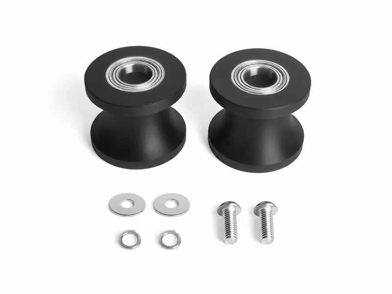
Many V wheels use two small bearings with a precision spacer or shim between them. The purpose of the stack is to support the wheel and allow the inner rings to be clamped without forcing the outer rings out of position.
The exact design varies. Buyers should inspect the complete stack rather than copying a generic arrangement.
Bearing Specification
Record:
- Bore, outside diameter and width
- Bearing series or controlled supplier drawing
- Ring and ball material
- Seal or shield type
- Internal clearance where relevant
- Lubrication requirement
- Permitted noise and play
- Quantity per wheel
A 2RS sealed bearing may help limit dust entry in a workshop. Its seal drag must be evaluated in the finished wheel. A stainless steel bearing may improve corrosion resistance, but it does not remove the need to review lubricant, seal and metal hardware.
Inner Spacer or Shim
If two bearings are clamped together, the central spacer controls the distance between their inner rings. A missing, short or inconsistent spacer can increase drag when the axle bolt is tightened.
The production check should compare rotation before and after the specified tightening procedure. If the wheel turns freely when loose and binds after assembly, the team should inspect the stack before changing the wheel material.
Axle and Mounting Bolt
The axle interface should control:
- Diameter and fit through the inner ring
- Supported length
- Straightness
- Thread position
- Shoulder or washer contact
- Tightening method
- Retention against loosening
The bolt should clamp the intended faces. Threads, burrs or tilted washers should not become bearing seats.
Fixed and Eccentric Spacers
Fixed spacers establish the reference row of wheels. Eccentric spacers provide adjustment on the opposing row. Their heights must place all wheel centre-lines in the intended plane.
Mixing wheel widths or spacer heights can create a carriage that appears assembled but binds because its wheels do not share one running plane.
Which Tolerances Matter in Repeat Production?
A buyer does not need the smallest possible tolerance on every dimension. The buyer needs controlled limits on features that affect interchangeability and motion.
ISO 286-1:2010 provides the current ISO system and terminology for tolerances and fits on linear sizes. ISO confirmed this edition again in June 2026. It can support the definition of shaft, bore and parallel-surface size relationships. It does not define the complete performance of a moulded V wheel or carriage.
The drawing and control plan should identify the functional characteristic, its limit and the inspection method.
Critical Wheel Characteristics
- Bearing-seat diameter and cylindricity
- Wheel width
- Bearing centre position
- V-profile angle and transition
- Effective profile relationship to the approved extrusion
- Radial run-out of the running surfaces
- Axial run-out or wobble
- Bearing retention after moulding or assembly
- Flash and gate condition near running faces
Critical Assembly Characteristics
- Mounting-hole centre distances
- Fixed-spacer and eccentric-spacer heights
- Plate flatness
- Axle perpendicularity to the plate
- Wheel centre-line alignment
- Available eccentric adjustment range
- Clearance between carriage and extrusion
Lot-Level Functional Check
A simple functional gauge can supplement dimensional inspection. For example, the supplier can use an approved extrusion section or a controlled mating gauge to check running contact and obvious interference.
The buyer should define the gauge revision, cleaning condition and acceptance method. A worn or unverified rail sample can create inconsistent results.
| Characteristic | Why it matters | Suitable control approach |
|---|---|---|
| Bearing seat | Retention and bearing stress | Bore gauge plus process control |
| V profile | Contact location and carriage height | Profile measurement or approved mating gauge |
| Radial run-out | Periodic force and motion variation | Dial indicator on an agreed datum |
| Axial wobble | Side contact and carriage instability | Face run-out check after assembly |
| Wheel width | Spacer and plate clearance | Calliper or dedicated gauge |
| Spacer height | Wheel centre-line position | Micrometre or height gauge |
| Hole pattern | Preload range and wheel sharing | CMM, fixture or positional gauge |
| Assembled drag | Detects stack and clamping problems | Defined torque and rotation test |
What Do Common Wear Patterns Reveal?
Wear patterns provide evidence about the wheel, rail and assembly. They should not be used alone to assign blame to one component.
Narrow Wear on One V Face
If one face carries most of the mark, inspect:
- Wheel and rail angle compatibility
- Axle perpendicularity
- Plate twist
- Rail alignment
- Off-centre drive force
- External moment on the carriage
Heavy Wear on Both Outer Lips
This may indicate an incorrect contact profile or excessive preload. Confirm whether the wheel is contacting where the design intended.
Groove Bottom or Root Contact
Root polishing can indicate that the rail tip or transition is bottoming in the wheel. The carriage may feel tight without stable two-face support.
Periodic Bump During Travel
A repeating bump at each wheel rotation can relate to:
- Radial run-out
- Local moulding deformation
- Contamination embedded in the surface
- A storage flat spot under high preload
- Bearing damage
Mark the wheel and rail so that the team can determine whether the disturbance follows the wheel rotation or remains at one rail position.
Black Dust or Debris
Debris may come from the wheel, belt, rail coating or environmental contamination. Inspect its source before changing the resin.
Movement Is Smooth Unloaded but Poor Under Cutting Force
This condition can indicate plate deflection, insufficient wheel spacing or a moment load beyond the intended light guidance system. A harder wheel may reduce local deformation but will not stiffen a weak frame.
| Observation | Likely investigation route | Avoid this premature conclusion |
|---|---|---|
| One-sided V-face wear | Alignment, angle and moment load | “The plastic is too soft” |
| Wheel binds after bolt tightening | Inner spacer and clamping faces | “The bearing is defective” |
| Drag changes along the axis | Rail straightness and frame parallelism | “All wheels are inconsistent” |
| Repeating bump | Wheel run-out, flat spot or bearing | “The extrusion is bent” |
| Carriage rocks at reversal | Preload, hole pattern and plate stiffness | “The wheel diameter is too small” |
| Rail becomes visibly marked | Contact position, filler and contamination | “Anodising is always unsuitable” |
What Does a Documented Material Investigation Teach V-Wheel Buyers?
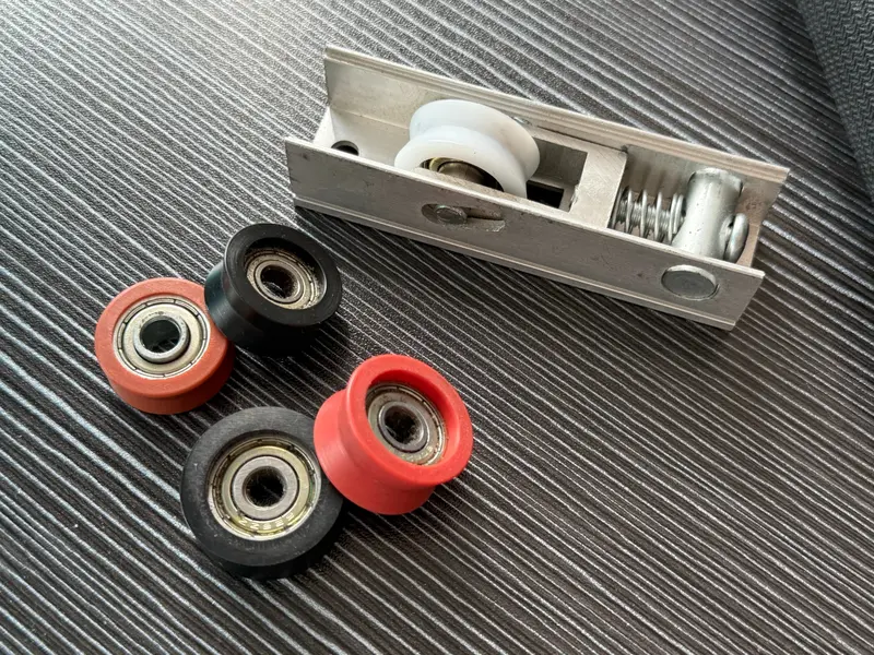
The following is a real, anonymised factory case. It did not involve a 3D printer or aluminium-extrusion carriage. We include it because it shows why a replacement wheel cannot be approved from a declared polymer name alone.
A customer sent us an original plastic component and stated that its outer material was POM with 30% glass fibre. We produced a sample according to that declared material. The finished sample differed from the original by more than 100 grams.
We did not treat the mass difference as a moulding adjustment problem. We sent both materials for analysis. The investigation found that the original material used POM with approximately 18% glass fibre and mineral filler, rather than the stated POM with 30% glass fibre.
Once the composition difference was identified, the mass discrepancy had a clear material cause. The project showed that two compounds carrying a similar broad name can produce different density, shrinkage, stiffness, surface and moulding behaviour.
What This Means for a V Groove Roller
This case does not prove that the investigated compound is suitable for a V wheel. It supports a procurement method:
- Treat the original sample as evidence, not a complete specification.
- Separate geometry comparison from material identification.
- Do not assume that mass variation comes only from mould settings.
- Define fillers and reinforcement when they affect contact or dimensions.
- Approve the real production grade before endurance testing.
- Keep the approved compound connected to the drawing and purchase order.
For an aluminium-rail wheel, filler type matters because the running surface contacts a relatively soft metal profile. A compound that is useful for a structural part may be unsuitable if reinforcement becomes exposed at the contact band.
If the buyer wants a functional duplicate of an existing wheel but cannot identify the material, laboratory analysis can reduce uncertainty. It still does not replace application testing.
How Should Buyers Approve a Production Sample?
The sample test should reproduce the real carriage geometry. A loose wheel spun between two fingers cannot reveal preload, plate distortion or rail mismatch.
Stage 1: Incoming Component Check
Record:
- Wheel identification and mould cavity where relevant
- Material grade and batch
- Bearing specification
- Wheel width and profile
- Run-out results
- Bearing retention
- Spacer and hardware dimensions
Stage 2: Assembly Check
Build the wheel into the production plate with the intended bolts, shims and spacers. Apply the defined tightening method.
Confirm:
- The wheels remain in one plane
- No wheel rubs against the plate
- Rotation does not change abnormally after clamping
- Eccentric adjustment covers the intended range
- The carriage can be fitted without forcing the rail or plate
Stage 3: Rail Fit and Preload Setting
Use production extrusion or a controlled approved rail sample. Define the adjustment sequence and acceptance criterion.
The operator should check:
- Free play at the carriage
- Rolling force or drive current
- Contact across every wheel
- Change in drag along the full axis
- Clearance between the plate and extrusion
Stage 4: Representative Dynamic Test
Run the system with the intended:
- Carriage mass
- Tool or payload offset
- Speed and acceleration
- Belt or screw drive
- Travel length
- Orientation
- Environmental contamination
The machine manufacturer should set the cycle count and acceptance limits. HUNE can manufacture and inspect the component, but the equipment manufacturer remains responsible for validating the full machine.
Stage 5: Post-Test Inspection
Compare:
- Contact-band position
- Wheel wear
- Rail marking
- Bearing noise
- Radial play
- Spacer movement
- Bolt retention
- Drive current or rolling resistance
- Dimensional change
Retain at least one approved assembly or clearly identified wheel set. The purchase order should refer to the same drawing, material and sample revision.
When Does a Custom Wheel Make Commercial Sense?
An existing V wheel is the simplest route when it matches the rail, bearing, spacer stack, carriage height and operating requirement. A custom mould becomes useful when a functional interface cannot be controlled with an existing part.
Consider dedicated tooling when:
- The rail profile is proprietary
- The contact position does not match a standard wheel
- The carriage height is fixed by an existing machine
- A different bearing changes the hub structure
- The required width affects the spacer stack
- The material grade needs separate shrinkage control
- Run-out or profile consistency needs a dedicated process
- The annual volume justifies controlled repeat production
- The buyer needs a protected part number and revision
Secondary machining may adjust an accessible width or surface on some wheels. It is usually a poor way to create a complete precision V running profile because machining can expose filler, change concentricity and add another tolerance chain.
| Sourcing route | Best used when | Main advantage | Main limitation |
|---|---|---|---|
| Existing wheel | Rail and assembly interfaces already match | Lowest development effort | Limited control over proprietary geometry |
| Existing wheel plus selected spacers | Wheel fits but carriage position needs adjustment | Uses available components | More stack-up points and hardware control |
| Prototype wheel | Contact geometry needs an early review | Fast learning before tooling | Prototype material may not represent moulded production |
| New injection mould | Profile, hub or material needs production control | Repeatable proprietary design | Tooling cost and approval time |
| Complete wheel-and-hardware assembly | Buyer needs one controlled supply unit | Simplifies incoming assembly content | Supplier needs the full plate and rail interfaces |
Buyers can review our OEM and ODM roller development process when comparing existing products, sample modification and new tooling. Our sliding rollers with bearing category also shows the broader structures that can be adapted for guide applications.
What Should a Supplier Comparison Sheet Contain?
Unit price alone does not show whether two quotations describe interchangeable wheel assemblies. Procurement teams should compare technical assumptions in one table.
| Comparison field | Supplier A | Supplier B | Buyer’s approved requirement |
|---|---|---|---|
| Rail profile used for review | |||
| V-profile drawing and revision | |||
| Maximum wheel envelope | |||
| Functional contact or gauge method | |||
| Wheel material and exact grade | |||
| Filler or reinforcement | |||
| Recycled content restriction | |||
| Bearing size and seal | |||
| Bearing material | |||
| Bearings per wheel | |||
| Inner shim or spacer | |||
| Fixed or eccentric spacer height | |||
| Run-out inspection | |||
| Mating-rail functional check | |||
| Sample quantity | |||
| Tooling ownership | |||
| Drawing change control | |||
| First-order quantity | |||
| Annual forecast | |||
| Packaging protection |
Information to Send With the RFQ
Send:
- Extrusion cross-section and supplier specification
- Carriage drawing with wheel-hole positions
- Wheel drawing or original sample
- Fixed and eccentric spacer dimensions
- Bearing and bolt requirements
- Carriage mass and external loads
- Tool or payload offset from the rail
- Speed, acceleration, travel and duty cycle
- Orientation of the axis
- Environmental and cleaning conditions
- Acceptance test and target life
- Sample, first-order and annual quantities
Photographs help us understand the assembly, but they cannot replace the extrusion and carriage drawings.
Final Release Checklist
| Release point | Approval question | Status |
|---|---|---|
| Application | Is this a light guidance system with defined limits? | ☐ |
| Rail | Is the production extrusion profile controlled? | ☐ |
| Contact | Have both V contact bands been reviewed? | ☐ |
| Clearance | Does the wheel avoid rail-tip and root interference? | ☐ |
| Geometry | Is the functional running relationship defined? | ☐ |
| Material | Is the exact resin grade approved? | ☐ |
| Filler | Are reinforcement and mineral fillers controlled? | ☐ |
| Bearing | Are size, material, seal and quantity recorded? | ☐ |
| Spacer | Is the two-bearing shim or spacer controlled? | ☐ |
| Hardware | Are bolt, washer and eccentric dimensions approved? | ☐ |
| Plate | Are flatness and mounting-hole positions controlled? | ☐ |
| Preload | Is there a repeatable adjustment method? | ☐ |
| Run-out | Are radial and axial limits agreed? | ☐ |
| Motion | Has drag been checked across the full rail? | ☐ |
| Load | Has the complete carriage load been calculated? | ☐ |
| Dynamic test | Were production speed and acceleration represented? | ☐ |
| Wear | Were wheel and rail contact marks inspected? | ☐ |
| Revision | Do the drawing, sample and purchase order agree? | ☐ |
| Responsibility | Has the machine manufacturer approved final use? | ☐ |
Conclusion
A v groove roller for aluminium extrusion should be specified as one part of a complete motion interface.
The buyer should match the V faces to the actual extrusion, control root clearance and understand the effective running position. The carriage should use a defined spacer stack and a repeatable preload method. The material specification should identify the real grade and fillers. The production plan should control profile, run-out, bearing retention and assembly drag.
The documented material-investigation case showed why a broad compound name can mislead a replacement project. The declared POM with 30% glass fibre did not match the original component, which contained a different glass-fibre level and mineral filler. That lesson applies directly to wheel procurement: geometry, compound and assembly must remain connected in the approval record.
A standard POM roller may work well in a light printer or engraver, but it should not be promoted as a universal linear-motion component. Desktop CNC loads, long gantries, harsh contamination or accuracy requirements may demand a different guidance system or more extensive validation.
If you are comparing a standard V wheel with a customised design, send us the extrusion cross-section, carriage drawing, wheel sample, spacer arrangement, load, speed and expected quantity. We can review the interfaces, identify missing controls and advise whether an existing wheel, prototype or dedicated mould is the practical next step.