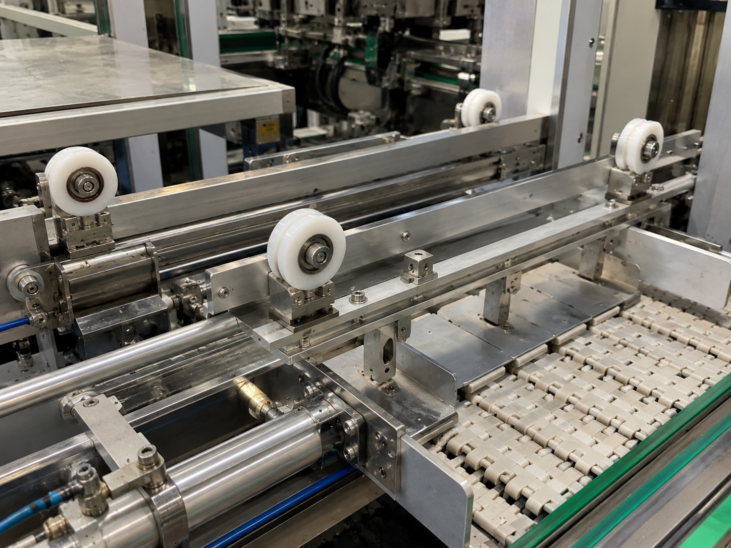
A plastic coated bearing can guide a product, belt, wire, tube or moving fixture in a compact conveyor and production-line mechanism. The plastic running surface protects the mating part and creates the required profile. The internal bearing reduces rotational resistance.
This simple description can hide several procurement risks. The wheel may carry a radial load, resist intermittent side contact or only correct occasional drift. Its surface may touch painted metal, aluminium, a polymer belt, insulated wire or an unfinished tube. These duties require different profiles, materials and acceptance tests.
At HUNE, Zhejiang Huaneng Micro Bearing Co., Ltd., we manufacture plastic-coated bearings, injection-moulded rollers, miniature bearings and customised roller assemblies. We do not select a guide wheel from the outside diameter alone. We first review what the wheel contacts, how the line moves and how the bearing is retained inside the moulded body.
This article helps equipment manufacturers, automation integrators, distributors and OEM procurement teams prepare a controlled specification. It focuses on light and medium guide duties. It does not assign a safety rating to a standard wheel or replace validation by the machine manufacturer.
What Job Does the Guide Roller Perform?
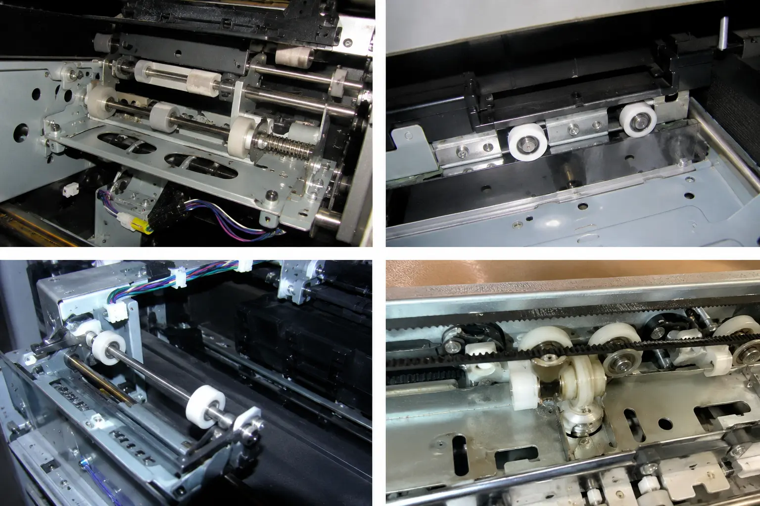
The term “conveyor roller” often suggests a roller that supports the full weight of a conveyed product. A small bearing roller may perform a different job. It may guide an edge, centre a tube, limit belt movement or stabilise a fixture during transfer.
Procurement should identify the exact duty before choosing a catalogue part.
| Guide position | Main function | Typical contact | Primary risk |
|---|---|---|---|
| Side guide | Corrects lateral drift | Product edge or carrier | Continuous side loading when alignment is poor |
| Belt edge guide | Limits belt movement | Belt edge | Edge damage, heat and bearing side load |
| Wire guide | Controls a moving wire path | Insulated or bare wire | Small groove, abrasion or sharp flange |
| Tube guide | Centres round stock | Metal or polymer tube | Surface marking and profile mismatch |
| Fixture guide | Locates a pallet or jig | Machined guide face | Impact at entry and dimensional variation |
| Limit roller | Prevents excess travel | Moving frame or mechanism | Shock contact and bracket deformation |
A side guide should not continuously force a badly aligned product back into position. Continuous hard contact can increase wear and transfer excessive force into the bearing, axle and bracket. The machine designer should correct the line geometry before using a harder roller as a substitute for alignment.
The buyer should also state whether the wheel is driven or freely rotating. This article addresses free-running guide rollers. A driven roller requires separate review of torque transfer, slip, shaft connection and acceleration.
What Must Buyers Define Before Requesting a Quote?
A useful request for quotation connects the component dimensions to the operating condition.
Product and Contact Information
Confirm:
- The part, belt, wire or tube that touches the wheel
- Contact material and surface finish
- Minimum and maximum product dimensions
- Permitted marking, scratching or colour transfer
- Contact direction
- Normal clearance before contact
- Whether contact is continuous or intermittent
A photograph shows the general arrangement. A section drawing shows the contact line, clearance and bracket relationship more clearly.
Motion and Duty
Provide:
- Line speed
- Roller speed, if calculated
- Operating hours per shift
- Start-stop frequency
- Reversal frequency
- Expected number of cycles
- Impact during product entry
- Planned maintenance interval
An intermittent limit wheel and a continuously rotating belt guide may share the same dimensions but require different bearings and materials.
Forces
The machine designer should define the expected radial force, possible axial force and entry impact. If exact values are not yet available, provide the mechanism layout and the method used to position the guide.
Do not use the bearing catalogue rating as the rating of the complete coated roller. ISO 281:2007 provides methods for rolling-bearing dynamic load ratings and rating life. The finished roller may instead be limited by the moulded hub, plastic creep, bearing retention, axle, bracket, impact or surface temperature.
Environment
State whether the assembly is exposed to:
- Dust, swarf or fibres
- Water or high humidity
- Oil, grease or coolant
- Cleaning chemicals
- Elevated or low temperatures
- Ultraviolet light
- Food-contact or cleanliness requirements
- Electrostatic-control requirements
These conditions must be part of the specification. A colour name or the word “nylon” does not define a controlled resin grade.
How Should the Contact Profile Match the Product?
The profile determines where the load enters the wheel.
Flat Running Surface
A flat or slightly crowned surface can support a broad, flat contact. It may suit a product edge, carrier or belt face when lateral retention comes from another feature.
A narrow flat wheel can create concentrated pressure. A very wide wheel can increase rubbing if its axis is not square to the movement.
Flanged Profile
A flange can limit lateral movement. It should not become a sharp rubbing edge during normal operation.
The drawing should define:
- Running diameter
- Flange diameter
- Contact width
- Edge radius
- Clearance to the guided part
- Permitted side contact
The buyer should inspect both the running surface and the flange after a line trial.
U or Rounded Groove
A rounded groove can guide wire, cable or tube. The groove must match the real finished diameter and permitted movement. A groove that is too narrow can pinch a coating. A groove that is too deep can trap contamination or create thin moulded walls near the flange.
V Profile
A V profile can centre a suitable round product or run against a matching track. It does not automatically suit every tube. Two narrow contact lines may mark a soft surface or create higher local stress.
| Contact requirement | Possible profile | Key confirmation | Unsuitable condition |
|---|---|---|---|
| Broad support or edge contact | Flat or crowned | Contact width and alignment | Sharp edge needs positive retention |
| Limited lateral movement | Single or double flange | Side clearance and flange radius | Continuous heavy rubbing |
| Round wire or tube guidance | Rounded groove | Finished diameter and minimum bend requirement | Groove pinches or bottoms on the product |
| Self-centring against a matching feature | V profile | Included angle and contact location | Soft or cosmetic surface is marked |
| Low-marking contact | Smooth radiused surface | Material and finish trial | Embedded debris remains on the wheel |
The effective running diameter may differ from the maximum outside diameter. Buyers should identify the actual contact point when calculating speed and installation height.
Which Plastic Material Should Buyers Consider?
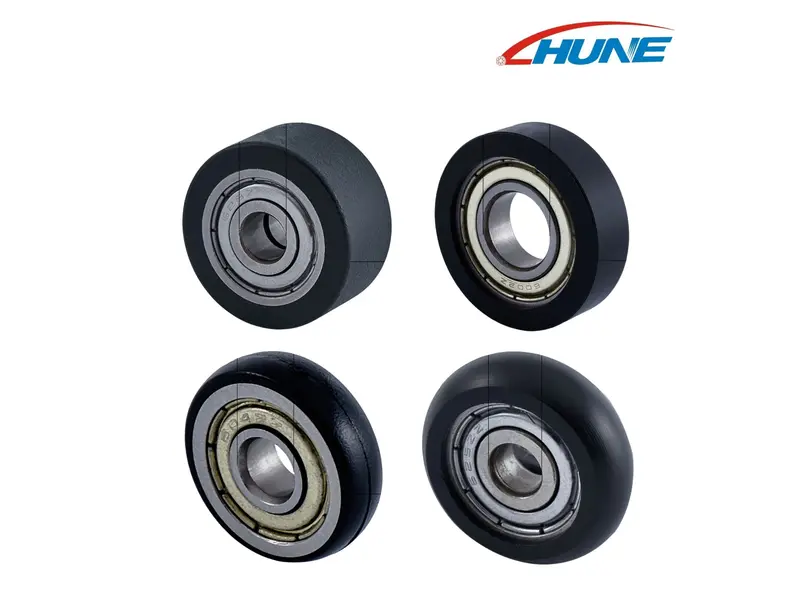
The outer material controls contact behaviour, wear, noise and dimensional stability. No single plastic is best for every production line.
POM
POM can provide low friction, good dimensional stability and a clean moulded surface. It is often considered for guide wheels and bearing rollers. The exact grade, filler and operating environment still matter.
PA or Nylon
PA materials can provide useful toughness and wear resistance. Moisture absorption can change dimensions and properties. Buyers should review conditioning and the actual humidity range when the clearance is small.
POK, PPSU, PEEK and Other Engineering Plastics
These materials may be considered when the application has a specific wear, temperature, chemical or dimensional requirement. Their higher material cost does not make them automatically better. The supplier needs a defined reason to select them.
Filled Materials
Glass fibre or mineral fillers can change stiffness, shrinkage, density, wear and surface behaviour. A filled compound may improve one property while creating a more abrasive contact surface.
If the roller touches a painted, coated or soft product, the buyer should test the real surface rather than approving the resin from a data sheet alone.
Material Selection Matrix
| Operating need | Property to evaluate | Validation method |
|---|---|---|
| Protect cosmetic product | Surface hardness, finish and contamination | Trial with actual product under agreed lighting |
| Maintain close clearance | Moisture response, creep and shrinkage | Conditioned dimensional inspection |
| Resist repeated wear | Compound and contact pressure | Representative-duration line test |
| Work near oil or coolant | Chemical compatibility | Exposure test with actual fluid |
| Run quietly | Surface hardness, bearing and alignment | Installed noise comparison |
| Control static-sensitive product | Electrical behaviour of complete material system | Application-specific measurement |
| Meet hygiene requirement | Exact grade, documents and cleanability | Buyer’s compliance and cleaning review |
At HUNE, we connect the approved material grade to the drawing and sample record. We do not treat two plastics of the same colour as equivalent.
How Does the Bearing Become Part of a Plastic Coated Bearing?
The connection between the bearing and plastic body often determines whether the roller remains stable in production.
Direct Overmoulding
Plastic can be moulded around the bearing. This method can create integrated retention and reduce a separate assembly step.
The tooling and process must protect the bearing. Excessive moulding pressure, heat or plastic shrinkage can affect rotation. Material must also flow around the bearing without leaving weak areas or unbalanced geometry.
Press-Fit Assembly
The bearing can be pressed into a moulded wheel after production. This method allows separate inspection and may make bearing replacement possible.
The interference must be controlled. Too little interference allows movement. Too much interference can reduce bearing internal clearance, crack the hub or distort the plastic body.
Mechanical Retention
A cover, shoulder, snap feature or fastener can retain the bearing. This can reduce reliance on interference alone, but it adds parts and assembly variables.
| Integration method | Advantage | Main risk | Inspection focus |
|---|---|---|---|
| Direct overmoulding | Integrated component and strong retention | Bearing affected by moulding or shrinkage | Rotation, runout and mould fill |
| Press-fit bearing | Separate production and flexible bearing choice | Fit too loose or too tight | Seat dimension and insertion force |
| Retaining cover | Positive axial retention | More parts and assembly error | Cover engagement and wheel clearance |
| Shoulder and fastener | Serviceable structure | Incorrect torque or spacer width | Installed rotation and axial play |
The buyer should specify whether bearing replacement is required. A permanently overmoulded bearing and a serviceable roller are different products even when their outside dimensions match.
Why Are Side Load and Alignment Important?
Most small radial bearings are selected primarily for radial rotation. A guide position can introduce axial or combined force when the wheel rubs against a flange or product edge.
Common causes include:
- Bracket mounted at an angle
- Product path not centred
- Belt tracking problem
- Wheel axis not square to travel
- Insufficient clearance
- Bent axle
- Excessive bracket flexibility
- Entry impact from an unlocated product
Installing a second bearing does not automatically correct alignment. Two bearing seats that are not coaxial can increase resistance.
The sample should be tested after the axle and bracket are fully tightened. A wheel that turns freely in the hand may bind after installation because the spacer is short or the bracket plates are not parallel.
The engineering team should also distinguish corrective contact from constant load. A side guide may touch the product occasionally. If it carries constant high force, the line may require redesign or a purpose-rated support roller.
Which Tolerances Control Repeatable Guidance?
A drawing with only outside diameter, width and bore does not control the functional assembly.
Useful dimensions can include:
- Effective running diameter
- Maximum outside diameter
- Contact width
- Groove width, depth and radius
- Flange diameter and thickness
- Bearing position
- Bearing-seat diameter
- Overall width
- Axial clearance after installation
- Radial runout of the completed roller
- Axial runout or face wobble
- Coaxiality for two-bearing structures
ISO 492:2023 defines dimensional and geometrical characteristics and tolerances for radial-bearing interfaces. It does not define the tolerance of the finished plastic-coated wheel. The buyer and roller supplier must separately agree the moulded component’s functional limits.
Do Not Apply Tight Tolerances Everywhere
Unnecessary precision increases inspection and production cost. The drawing should identify the characteristics that influence guidance.
For example, the moulded colour may have a broad cosmetic tolerance while the running diameter and bearing position require controlled limits. A non-contact side face may not need the same runout requirement as the working surface.
Measure the Completed Component
Separate parts can pass inspection while the finished roller runs eccentrically. The supplier should measure critical characteristics after the bearing and plastic body form the completed component.
What Can a Real Thick-Wall Moulding Review Teach Buyers?
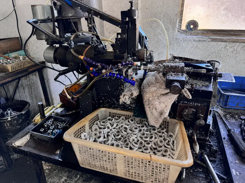
The following is a real HUNE custom-product development case. The customer’s final application was not documented as a conveyor system, so we do not present it as a conveyor customer case. It demonstrates a manufacturing issue that also matters when buyers design a plastic coated bearing.
The customer provided a drawing for a customised ABS plastic wheel. Our mould team reviewed the central section and found that it was too thick for stable injection moulding. The thick mass could cool more slowly than the surrounding area and create a visible depression or sink condition.
Information Available
The project included:
- A customised plastic wheel geometry
- An internal bearing requirement
- ABS-based outer material
- A thick central section
- A final drawing that controlled the mould development
Our Engineering Review
We explained that the geometry created a cooling risk. We offered two routes:
- Reduce the thickness of the central section in the 3D design.
- Keep the original dimensions and accept the likely depression.
The decision had to be made before the mould structure was fixed. Appearance, wall thickness, bearing support and dimensional function could not be reviewed independently.
Procurement Lesson
A thick plastic section is not automatically stronger or more stable. Uneven wall thickness can create:
- Different cooling rates
- Sink marks
- Internal stress
- Dimensional variation
- Longer moulding cycles
- Unpredictable bearing-seat behaviour
For a conveyor guide roller, the buyer should ask the supplier to review the section around the bearing, groove and flanges before tooling. A drawing approval should include manufacturability, not only nominal dimensions.
How Should Buyers Diagnose Common Problems?
The observed symptom should guide the investigation. Changing plastic or bearing size without identifying the cause can move the failure elsewhere.
| Observed problem | Likely areas to inspect first | Avoid this assumption |
|---|---|---|
| Product edge becomes marked | Contact pressure, debris, profile and material | A softer plastic will always solve it |
| Wheel becomes noisy | Bearing fit, contamination, bracket and alignment | Noise always means a low-quality bearing |
| Roller stops turning | Axle torque, side contact, bearing seat and debris | A larger bearing is the only answer |
| Plastic body cracks near bearing | Excessive interference, wall thickness or impact | Thicker plastic always prevents cracking |
| Bearing moves inside wheel | Seat tolerance, creep and retention method | Adhesive alone will provide permanent control |
| One flange wears rapidly | Constant side load or misaligned product path | A harder flange will correct tracking |
| Product oscillates | Runout, wheel spacing or bracket stiffness | The outside diameter is the only critical dimension |
| Wheel diameter changes | Temperature, moisture, creep or chemical exposure | All plastics remain dimensionally unchanged |
| Belt edge frays | Sharp flange, excessive side force or tracking error | The roller material is the sole cause |
Bearing Noise
Listen to the roller in the installed assembly. Remove the product contact temporarily if the machine allows a safe diagnostic check. This can help separate bearing noise from rubbing noise.
Local Wear
Mark the wheel orientation and compare the wear position after operation. Wear around the full circumference suggests a contact or material issue. Wear at one side suggests alignment or clearance. A single local defect may relate to moulding, impact or embedded debris.
Heat
Heat can come from bearing preload, seal friction, excessive line speed, sliding contact or an over-tight axle. Temperature should be measured under controlled conditions rather than judged only by touch.
How Should Samples Be Tested on the Line?
A sample programme should reproduce the real contact and installation.
1. Incoming Dimensional Check
Measure the drawing characteristics that affect function. Record the method, instrument and sample condition. Plastics that respond to moisture or temperature should be measured under an agreed condition.
2. Free-Rotation Check
Check bearing rotation before and after installation. A change after tightening can reveal a spacer, bracket or axle problem.
3. Static Contact Check
Place the real product, belt, wire or tube against the wheel. Confirm the contact line, clearance, flange relationship and absence of sharp edges.
4. Low-Speed Trial
Run the machine slowly where the design permits. Observe entry impact, product drift, wheel rotation and unexpected side contact.
5. Production-Speed Trial
Increase to the intended operating range using the machine manufacturer’s safe validation procedure. Record:
- Noise
- Temperature
- Product tracking
- Surface marking
- Roller vibration
- Bearing rotation
- Bracket movement
6. Representative-Duration Test
A short trial may not reveal creep, moisture response, contamination or heat. Run a duration that represents the planned duty and inspect the component at defined intervals.
7. Changeover Test
If the line handles several product sizes, test the minimum, maximum and most sensitive products. A guide setting that works for one size may overload another.
8. Post-Test Inspection
Inspect:
- Running surface
- Flanges or groove
- Product surface
- Bearing rotation
- Bearing position
- Hub condition
- Axle and spacer
- Bracket alignment
- Debris accumulation
9. Retained Sample and Revision Record
The buyer and supplier should retain an approved sample. The record should state the drawing revision, resin grade, bearing, colour, critical dimensions, test machine and approved deviations.
When Is a Custom Mould Justified?
An existing roller is the lowest-risk route when the profile, material, bearing and installation already fit the mechanism.
A custom mould becomes reasonable when the function cannot be controlled with an existing product.
| Development route | Suitable condition | Main limitation |
|---|---|---|
| Existing roller | Profile, bearing and installation match | Limited design and material options |
| Existing roller with machining | One accessible dimension needs a small adjustment | Added cost and reduced wall thickness |
| New moulded outer wheel | Contact geometry or material must change | Tooling and sample approval are required |
| Direct overmoulded bearing | Integrated retention supports volume production | Bearing and moulding process need joint control |
| Complete roller assembly | Wheel, axle, spacer and bracket interact | More drawings and validation are required |
| Prototype geometry | Contact relationship remains uncertain | Prototype behaviour may differ from moulded production resin |
Freeze these items before tooling:
- Contact profile
- Effective running diameter
- Bearing model
- Axle and bracket space
- Material grade
- Critical wall thickness
- Moulding or assembly route
- Required quantity
- Test and approval plan
Changing the bearing after mould completion can affect the hub wall, overall width and running diameter. Changing from unfilled to filled resin can also affect shrinkage and surface behaviour.
Buyers can review our OEM and ODM roller manufacturing process when comparing an existing product, secondary machining and new tooling.
They can also compare relevant structures in our sliding rollers with bearing category before deciding whether a standard component can meet the guide duty.
What Should Buyers Compare Between Suppliers?
Two suppliers can quote the same outside dimensions but include different materials, bearings and controls.
| Quotation item | Information to compare |
|---|---|
| Application assumption | Guided product and roller function |
| Plastic | Exact resin, filler, colour and recycled-content restriction |
| Bearing | Model, material, seal or shield and quantity |
| Construction | Overmoulded, press-fit or mechanically retained |
| Profile | Contact geometry and edge radii |
| Tolerance | Running diameter, width, bearing position and runout |
| Inspection | Sample size and controlled characteristics |
| Functional test | Rotation, retention, contact or line test |
| Tooling | Included mould components and ownership |
| Sample | Quantity, lead time and revision status |
| Production | MOQ, capacity and change-control method |
| Packaging | Protection from impact, deformation and contamination |
A quotation is not comparable if one supplier uses a generic unfilled material and another uses a controlled filled grade. The same applies when one quotation includes a sealed bearing and another does not identify the closure.
Ask each supplier to state assumptions and deviations in writing.
Final RFQ and Release Checklist
| Approval item | Confirmation question | Status |
|---|---|---|
| Machine | Is the equipment and roller position identified? | ☐ |
| Function | Does the roller guide, limit, centre or support? | ☐ |
| Contact | Is the guided product and surface material known? | ☐ |
| Profile | Is the contact geometry approved? | ☐ |
| Clearance | Is the normal running clearance defined? | ☐ |
| Force | Are radial, side and impact conditions understood? | ☐ |
| Speed | Is the operating speed confirmed? | ☐ |
| Duty | Are hours, cycles and reversals known? | ☐ |
| Environment | Are dust, liquid, temperature and chemicals recorded? | ☐ |
| Plastic | Is the exact resin grade approved? | ☐ |
| Bearing | Are model, material and closure confirmed? | ☐ |
| Construction | Is the bearing-retention method approved? | ☐ |
| Axle | Are diameter, tolerance and tightening method defined? | ☐ |
| Bracket | Are alignment and stiffness sufficient? | ☐ |
| Dimensions | Are functional dimensions and tolerances stated? | ☐ |
| Runout | Is the completed roller limit measurable? | ☐ |
| Tooling | Has wall thickness and mouldability been reviewed? | ☐ |
| Sample | Was the component tested in the intended assembly? | ☐ |
| Product range | Were all relevant line changeovers tested? | ☐ |
| Duration | Was the trial long enough to reveal heat and wear? | ☐ |
| Retained sample | Do both parties keep an approved sample? | ☐ |
| Revision | Does the order refer to the approved drawing revision? | ☐ |
| Release | Has the machine manufacturer approved production? | ☐ |
Conclusion
A plastic coated bearing for a conveyor guide system should be specified from its contact duty, not from its outside diameter alone.
The buyer should define what the wheel touches, whether contact is continuous, the expected side force, line speed and environment. The profile should support the real product without pinching, marking or creating constant flange friction. The material should provide the required surface and dimensional behaviour. The bearing, plastic body, axle and bracket must work as one installed assembly.
Our thick-wall moulding review showed why a nominally strong section may still create cooling and dimensional risk. Buyers should complete this manufacturability review before approving tooling.
The sample should then run with the intended product, speed, bracket and changeover range. The machine manufacturer remains responsible for validating the complete mechanism and any safety-related function.
If you are sourcing a standard or customised conveyor guide roller, send us the assembly drawing, contact material, speed, expected forces, environment, bearing requirement and order quantity. We can review whether an existing wheel is suitable or whether the project needs machining, a new mould or a complete custom assembly.


[…] all influence whether the complete assembly rotates freely and follows the intended path. A plastic-coated bearing guide system for conveyors explains how to define contact duty and mating geometry. If the application uses a round rail or […]
[…] a conveyor guide, the mating profile and contact duty should be specified together; our guide to plastic-coated bearings for conveyor guide systems explains those considerations. Our overview of what a bearing roller is also distinguishes a […]
[…] to splash, detergent, debris or washdown even when they do not touch the conveyed product. HUNE’s conveyor guide roller system and bearing roller product range can be evaluated for suitable guide or support functions, subject […]