

Why do drawer slides bind under load even when they move freely while empty? The added mass bends the drawer, cabinet or slide members and changes the alignment between the two running paths. A small side-clearance error, twisted mounting surface or uneven load then becomes internal preload. Balls or rollers are forced against their races, operating force rises, and the drawer may rack or stop.
> The short engineering answer: binding under load is usually a system-geometry problem before it is a bearing problem. Check total moving mass, load position, drawer stiffness, cabinet stiffness, rail parallelism, side clearance, mounting orientation and slide deflection together.
For OEM development, the correct response is not to loosen the assembly until it moves. It is to identify which functional dimension or structural member changes when the load is applied, then validate the complete drawer, slide pair and cabinet under representative conditions.
Why Does Load Turn a Small Error Into Binding?
Load changes the geometry that the slide needs in order to roll. An unloaded drawer can hide errors that become significant at full extension.
A side-mounted telescopic slide contains nested steel members with rolling elements between them. The left and right slides should travel on compatible, nearly parallel paths. When a drawer is loaded, several things can happen at once:
- the drawer bottom and sidewalls deflect;
- the front or rear of the drawer racks out of square;
- the cabinet sides move inward or outward;
- the extended rail members sag;
- the load shifts the drawer's center of gravity away from the slide pair;
- the mounting screws pull a thin rail against an uneven surface;
- the balls or rollers move toward one side of their intended contact zone.
The rolling elements then carry not only the intended load but also forces created by misalignment. This is why replacing a nominally “weak” bearing does not necessarily solve the problem. A higher-capacity slide can still bind if the cabinet forces the two rails into different planes.
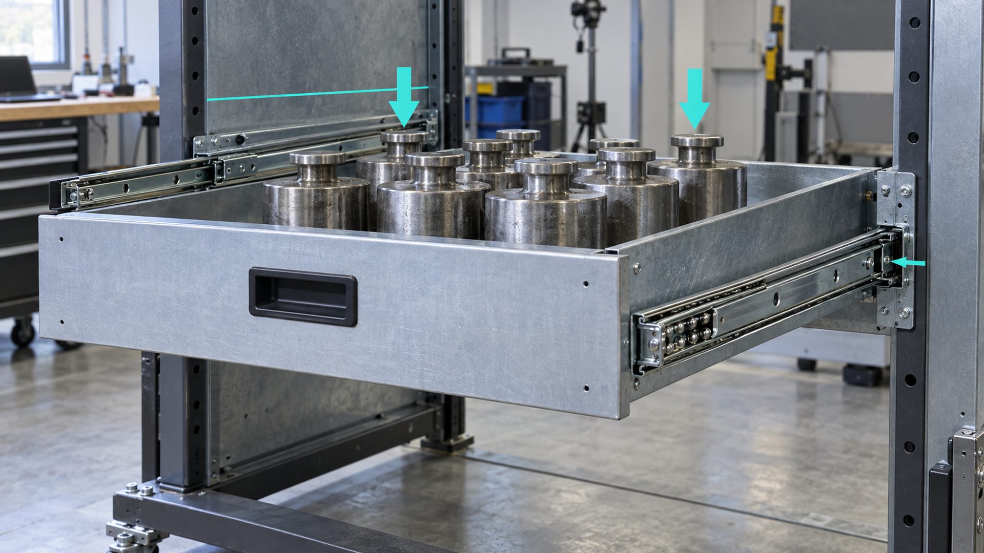
I normally separate three questions during diagnosis:
- Does each slide move smoothly by itself? This checks the rail assembly before it is coupled through the drawer.
- Does the empty installed drawer move smoothly? This adds mounting geometry and drawer squareness.
- At what load and extension does resistance begin? This shows when deflection, load position or internal contact starts to dominate.
That sequence is useful for engineering analysis. It should not be treated as a substitute for the product's formal validation plan.
Which Parts Form the Drawer-Slide System?
The slide pair is only one part of the load path. The drawer, cabinet, brackets and fasteners determine whether the rails stay aligned.
The complete load path is:
contents → drawer bottom and sidewalls → moving slide members → rolling elements → fixed slide members → brackets or mounting screws → cabinet structure
| System element | What it controls | How it can contribute to binding |
|---|---|---|
| Drawer bottom | Supports contents and distributes load | Sag pulls the sidewalls inward or twists the box |
| Drawer sidewalls | Carry the moving slide members | Bowing changes clearance and rail straightness |
| Drawer front and rear | Keep the box square | Weak joints allow racking under an offset pull |
| Moving rail members | Transfer drawer load into the rolling elements | Thin or long members can deflect at extension |
| Ball cage, rollers or bearing wheels | Provide rolling contact and spacing | Uneven contact, damage or incorrect preload raises resistance |
| Fixed rail members | Establish the cabinet-side running paths | Non-parallel or twisted mounting produces cross-load |
| Brackets and fasteners | Position and retain the rails | Missing fixings or distorted brackets permit local movement |
| Cabinet sides or machine frame | Provide the mounting datums | Deflection changes rail spacing under load |
| Stops, disconnects and soft-close parts | Control travel and closing behavior | Incorrect position can create a local hard point |
A buyer should therefore describe the actual drawer and enclosure. A slide tested on a rigid fixture may behave differently when mounted to a wide timber cabinet, thin sheet-metal enclosure or plastic housing.
What Are the Most Common Engineering Causes?
Most loaded binding comes from one or more of six conditions: insufficient clearance, loss of parallelism, structural deflection, unsuitable load assumptions, distorted rail geometry or rolling-contact interference.
1. Side Clearance Is Too Small or Unequal
Side-mounted slides need a defined space between the drawer and cabinet. If that space is smaller than the slide system requires, the rails are squeezed together. If it is larger, screws may pull the rails outward and twist them. Unequal left and right clearance can rotate the drawer relative to the cabinet.
I treat side space as a functional stack, not a single cabinet dimension. It includes:
- cabinet internal width;
- drawer external width;
- slide-pair installed thickness;
- drawer and cabinet squareness;
- coating, edge banding or finish thickness;
- manufacturing variation;
- moisture-related movement where wood-based panels are used.
The correct nominal clearance and tolerance come from the selected slide specification and the product stack-up. I would not publish one universal gap for all slide types.
2. The Rails Are Not Parallel or Coplanar
The two fixed members may be parallel in plan view yet sit at different heights or angles. One mounting surface can also twist along its length. When the drawer connects both sides, it forces the moving members to follow incompatible paths.
A slight error may be tolerated while empty because the slide clearances absorb it. Under load, the rolling contacts move to the edge of the available clearance and friction rises sharply. Long slides and full-extension designs often reveal these errors more clearly because the extended structure creates a larger bending moment.
3. The Drawer or Cabinet Deflects
A load rating for the slide does not guarantee that the drawer box or enclosure is stiff enough. A wide drawer can sag in the middle. A tall, narrow sheet-metal sidewall can bow. A cabinet without adequate cross-bracing can rack when the drawer is extended.
The resulting movement can reduce side clearance, shift the rail axes or load one slide more heavily than the other. I normally measure geometry both unloaded and at representative load, especially at full extension where structural leverage is greatest.
4. The Load Is Off-Centre or Moves During Travel
A load concentrated near one front corner does not act like the same mass distributed evenly. It can twist the drawer and create unequal reactions at the two slide pairs. Mobile contents can also shift as the drawer accelerates or hits a stop.
The gross moving mass should include the drawer itself, contents, inserts, front panel, handles and any mounted equipment. For mobile machinery or vehicle applications, acceleration, vibration and impact may matter as much as static mass.
5. The Slide Is Used in a Different Orientation
Side-mount, flat-mount and undermount arrangements do not load the rail cross-section in the same way. A slide that carries load effectively on its side may deflect much more when laid flat. Accuride's technical selection guidance states that mounting orientation affects performance and recommends application testing, especially for flat mounting and deflection.
The supplier's load rating should therefore be read with its stated orientation, slide length, extension, mounting method and test conditions. “Rated for the load” is incomplete without those conditions.
6. The Rolling Path Has Local Interference
Binding at one repeatable travel position can indicate a local rail dent, burr, coating buildup, deformed ball retainer, incorrect stop, displaced soft-close trigger or contamination. In roller-slide designs, the wheel profile may climb a flange or contact a rail edge under load.
Lubrication can affect movement, but extra lubricant cannot correct incompatible geometry. It may also attract debris or contaminate adjacent furniture surfaces. Use only the lubricant and maintenance method specified for the slide design.
How Can the Binding Pattern Identify the Cause?
Where and when resistance appears provides useful evidence, but the symptom should be confirmed by measurement.
| Observed behavior | Likely engineering area to inspect | Confirmation method |
|---|---|---|
| Smooth empty, tight when loaded | Structural deflection, insufficient clearance, off-centre load | Compare loaded and unloaded rail spacing and drawer squareness |
| Tight only near full extension | Extended-member deflection, cabinet racking, stop interference | Measure sag and rail alignment at progressive extensions |
| Hard point at the same position | Rail damage, local burr, cage or trigger interference | Inspect and operate each slide separately through that position |
| One side moves before the other | Drawer racking, unequal load or rail height | Check diagonal dimensions, load position and both mounting datums |
| Operating force rises gradually | Increasing deflection or rolling-contact preload | Record force and geometry across travel and load levels |
| Noise plus rough movement | Contamination, damaged rolling path, poor wheel-track contact | Inspect running surfaces, balls, cages, rollers and lubrication condition |
| Drawer rebounds or will not close fully | Soft-close, detent, stop or cabinet-square issue | Isolate the auxiliary mechanism and check closing geometry |
A hand-pull comparison is useful during development, but a controlled force measurement gives more reliable evidence. The fixture, pull direction, speed, load position and extension should be defined so that samples can be compared.
Are Ball-Bearing Slides and Roller Slides the Same?
No. Both reduce sliding friction through rolling contact, but their running geometry and component supply chain are different.
A telescopic ball-bearing slide normally uses rows of loose balls retained between formed steel channels. Its balls circulate or translate within the nested members; it does not usually contain a conventional deep-groove ball bearing as a separate wheel.
A roller slide uses discrete wheels running in formed tracks. The wheel may be a plain polymer roller, a metal wheel or a plastic-coated bearing roller. In that architecture, wheel diameter, tread profile, axle, bracket and track section become important functional interfaces.
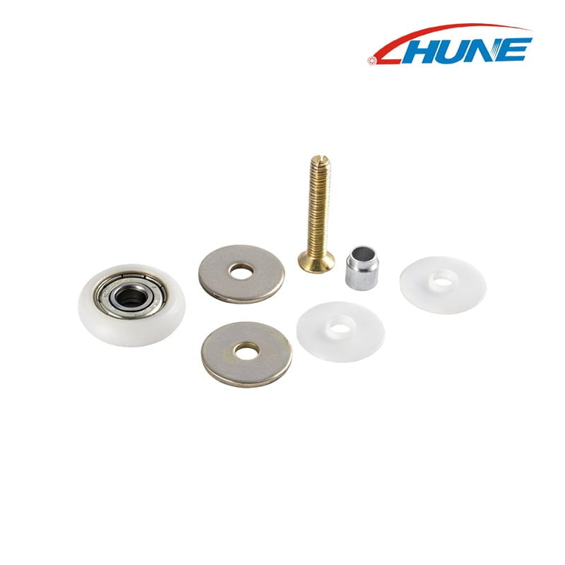
HUNE manufactures custom roller assemblies, bearings and stamped hardware. The component stack shown below—a bearing-supported wheel, shaft, washers and polymer parts—illustrates a roller-slide building block. It should not be presented as a direct replacement for the rolling elements inside a conventional telescopic ball-bearing channel.
For roller-guided drawers, pull-outs or equipment trays, a custom stamped roller component can be designed around the approved wheel, axle and rail interface. Where a discrete bearing wheel is required, HUNE's 6900-series deep-groove bearing page shows the bearing category available for project review. The bearing number alone still does not define the finished roller or its load capability.
The related guide on where deep-groove ball bearings are used explains why the bearing, wheel, shaft, bracket and track should be evaluated as one mechanism.
Which Functional Dimensions Should the Drawing Control?
The drawing should control rail position and the rolling interface through shared datums. Cosmetic dimensions should not consume tolerance that the functional stack needs.
| Drawing control | Why it matters under load | Suitable review method |
|---|---|---|
| Cabinet-side mounting datum | Establishes fixed-rail plane | Fixture, straightedge or coordinate measurement |
| Drawer-side mounting datum | Establishes moving-rail plane | Measure relative to drawer bottom and side |
| Installed distance between slide members | Controls lateral preload | Check at front, middle and rear |
| Rail parallelism | Keeps both sides on compatible paths | Compare axes over the full mounted length |
| Rail height difference | Prevents drawer twist | Level or fixture measurement from a common base |
| Drawer width and squareness | Controls side clearance and racking | Width at several locations and diagonal comparison |
| Slide-member straightness | Protects the rolling path | Free-state and installed checks |
| Mounting-hole location | Controls rail position and adjustment | Functional gauge or coordinate inspection |
| Fastener-head envelope | Prevents member or cage contact | Full-travel clearance check |
| Roller diameter/profile, if used | Sets track contact and running height | Diameter and profile inspection at the running surface |
| Axle and bearing retention, if used | Controls alignment and free rotation | Assembly fixture and rotation check |
| Stop and soft-close trigger position | Controls engagement at travel limits | Installed functional check |
I also distinguish between free-state dimensions and installed dimensions. A stamped rail may meet its drawing before assembly but distort when screws pull it against an uneven cabinet wall. The installed check is the one that represents the actual running condition.
For custom roller-based hardware, HUNE's roller material and process guide outlines how bearing fit, moulded wheel geometry, stamped parts and final assembly are coordinated. Those interfaces should appear on an assembly drawing rather than remain as informal supplier assumptions.
How Should Load Rating Be Read?
A load rating is valid only with its stated configuration and test conditions. It is not an interchangeable property of any slide with a similar cross-section.
Before selecting a slide, confirm:
- whether the rating applies to one slide or a matched pair;
- whether drawer mass is included in the stated load;
- slide length and extension condition;
- side-mount, flat-mount or other orientation;
- mounting-hole usage and supporting structure;
- load distribution and center of gravity;
- expected cycle count and operating speed;
- maximum allowable deflection or operating force;
- temperature, contamination, corrosion and vibration conditions;
- whether stops, locks or soft-close devices are included.
ISO 12808:2024 specifies strength and durability test methods and requirements for furniture extension elements and their components. For the North American cabinet-hardware context, the ANSI/BHMA A156.9-2026 overview describes operational, cycle and strength criteria and includes drawer-slide classifications. If a project requires compliance, use the full applicable standard and its defined fixture and classification rather than relying on the summary page.
A supplier's published rating can screen options. Final approval still requires the intended drawer and enclosure because the standard or catalogue fixture may be stiffer and more controlled than the production product.
How Should an OEM Validate a Drawer-Slide System?
Test the complete assembly progressively: first geometry, then unloaded movement, then representative load and duty. This makes the cause of binding visible before mass production.
- Requirement review: define drawer size, gross moving mass, load distribution, extension, orientation, environment and target life.
- Interface review: confirm rail type, mounting datums, side-clearance stack, fasteners, stops and auxiliary mechanisms.
- Free-state inspection: check each slide's movement, straightness and visible running condition before installation.
- Installed unloaded check: measure the mounted rails and drawer box, then operate through full travel.
- Progressive load test: add load in controlled steps and record operating force, deflection, noise and the point where resistance changes.
- Worst-position check: evaluate full extension and any defined offset or moving load condition.
- Cycle and stop testing: use the applicable customer requirement or standard, then inspect wear, deformation and retention.
- Pilot-production review: repeat the installed test across multiple assemblies to reveal manufacturing variation.
- Release control: freeze the drawing revision, approved sample, material and finish specifications, inspection plan and change process.
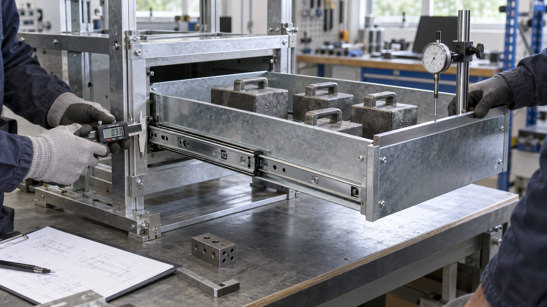
I would not approve a design from one unloaded prototype. A geometry prototype answers whether the parts fit; a production-intent, loaded assembly answers whether the complete system continues to move as intended.
What Should a Buyer Send the Supplier?
A useful enquiry defines the slide architecture and the product around it. A photograph of a jammed drawer is not enough for component selection.
Send as many of the following as possible:
- assembly drawing and 3D model with revision level;
- drawer and cabinet dimensions, materials and wall thicknesses;
- total moving mass and expected content load;
- load position, drawer width, slide length and extension;
- required mounting orientation and available envelope;
- existing slide, roller, bearing or stamped-part samples;
- rail cross-section and mounting-hole pattern;
- critical clearances, datums and inspection methods;
- required operating force, noise or deflection acceptance criteria;
- cycle, static-load, impact or stop-test requirement;
- corrosion, temperature, dust and lubrication conditions;
- first-order quantity, annual demand and expected product life;
- packaging, labeling and traceability requirements.
For a custom roller or stamped bracket, also provide the roller profile, axle structure, bearing arrangement, track contact and assembly method. HUNE's OEM manufacturing process shows how drawings, samples, bearings, moulded wheels, stamped parts and final inspection can be managed as one project.
Frequently Asked Questions
Can a drawer slide be correctly rated and still bind?
Yes. A rating assumes defined mounting, orientation, load and test conditions. The production drawer can still bind if its side clearance is wrong, the rails are not parallel, the cabinet deflects, the load is offset or the mounting surface twists a rail. Rating selection and geometry validation are separate tasks. Confirm the complete moving mass first, then measure the installed system unloaded and under representative load.
Why does a drawer bind only at full extension?
Full extension usually creates the largest bending moment in the slide members, drawer and cabinet. Deflection can reduce side clearance or move the two rails out of parallel. A stop, disconnect or soft-close component may also create local interference near the end of travel. Measure rail height, spacing and drawer squareness at several extensions, and compare the behavior with each slide operated independently.
Do wider drawers need different slide validation?
Yes. A wider drawer gives an offset load more leverage to rack the box and load one slide more than the other. The drawer bottom and front/rear joints also have a longer span. Slide capacity alone does not confirm that the drawer stays square. A representative loaded test should include the actual width, stiffness, load distribution and pull position.
Can a bearing upgrade solve loaded binding?
Only when the existing rolling element is the verified limitation. A bearing with greater capacity cannot straighten a twisted rail, restore missing clearance or prevent a flexible cabinet from racking. In a discrete roller design, the bearing must also match the axle, wheel, bracket and track. First identify whether the resistance comes from the rolling element, contact profile or surrounding structure.
Prevent Binding by Controlling the Loaded Geometry
Drawer slides bind under load when the rolling paths no longer remain compatible. The most important variables are side clearance, rail parallelism, drawer and cabinet stiffness, extension, mounting orientation, load distribution and the exact ball or roller interface.
For an OEM project, measure those conditions before changing the component. Then validate a representative drawer progressively from unloaded travel to full-extension load and cycle testing. If the design uses custom bearing rollers, stamped brackets or track components, HUNE can review the component stack against the complete mechanism.
Send the assembly drawing, rail cross-section, drawer size, load position, required extension, critical datums, environment, validation target and expected quantity through the HUNE engineering enquiry page. This information makes it possible to determine whether an existing bearing or roller structure, a modified stamped component or new tooling is the appropriate sourcing route.


