

What does “one-stop bearing integration” mean?
A one-stop bearing roller solution is a coordinated process for specifying, developing, assembling and supplying the bearing, wheel or roller, mounting hardware and related production controls as one approved OEM assembly. It does not simply mean buying a standard bearing from one seller. The supplier must understand the mating track or shaft, load direction, motion, material, environment, assembly fit, inspection plan and repeat-order requirements.
For OEM buyers, the goal is to reduce interface gaps between separate component suppliers. A bearing can meet its own drawing and still perform poorly inside a roller if the wheel profile, bearing seat, axle, bracket or track is wrong. I start with the complete mechanism and identify which dimensions control the installed movement. Then I decide what should be standardized, customized, assembled and validated together.
Why integrate the bearing and roller supply?
Integration is most useful when component interfaces, supplier handoffs or assembly responsibility create avoidable project risk. A buyer sourcing a bearing, moulded wheel, shaft, stamped bracket, surface treatment and final assembly separately may need to reconcile different drawings, revisions, inspection methods and delivery schedules.
A coordinated supplier can review the assembly as a whole and keep component decisions connected. That may simplify sourcing and make engineering changes easier to control. It does not automatically lower unit price, remove the need for customer approval or guarantee service life. The commercial case depends on tooling, annual demand, component complexity, incoming inspection, assembly labour, scrap, packaging and the cost of managing multiple suppliers.
| Sourcing model | Where it can work well | What the buyer must control |
|---|---|---|
| Separate component suppliers | Standard bearings and simple, stable designs with strong internal engineering resources | Interface drawings, supplier coordination, incoming inspection and assembly responsibility |
| Bearing supplier plus external roller assembler | Projects where the bearing supplier is capable but the wheel or bracket needs a specialist | Bearing-to-wheel fit, drawing ownership, change notices, traceability and corrective-action route |
| One coordinated bearing-roller supplier | Custom wheel profiles, integrated hardware or repeated OEM assemblies with several linked interfaces | Scope boundaries, approved specifications, validation evidence, component traceability and change control |
The right model is the one that gives the OEM clear control of critical interfaces and quality records. “One supplier” is useful only when it comes with a defined scope and accountable process.
What belongs in an integrated bearing roller assembly?
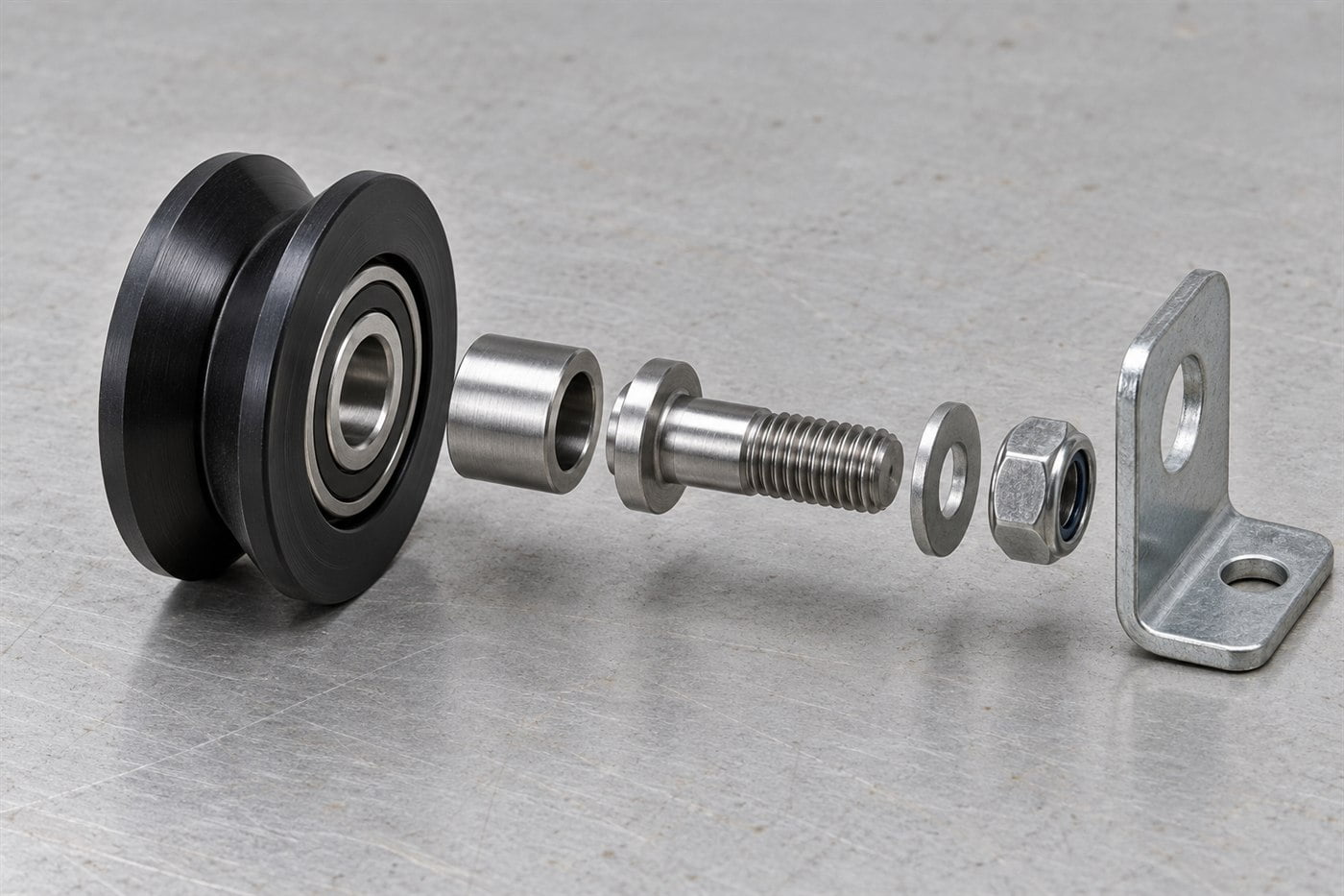
Define the assembly by function, not by a product name or bearing number. A typical bearing-integrated roller may include a rolling bearing, polymer or coated wheel, axle or threaded stud, spacer, retainer and bracket. Some applications also involve a guide track, rail, shaft, housing or adjacent hardware. Each item influences fit and motion.
| Element | Functional question to resolve | Drawing or specification detail to control |
|---|---|---|
| Bearing | What radial and axial loads, speed, duty cycle and environment will it see? | Bearing reference or required envelope, seal/shield, clearance and supplier documentation |
| Roller outer body | Which surface contacts the track, cable, panel or product? | Running diameter, width, groove/profile, material grade, surface condition and critical contact geometry |
| Bearing seat / hub | How is the bearing retained and how does the wheel rotate concentrically? | Seat diameter, depth, shoulder, retention method, runout or concentricity requirement where functionally necessary |
| Axle, stud or shaft | How is the assembly mounted and what carries the load? | Diameter, length, thread, shoulder, fit, material and mounting datum |
| Bracket / housing | Does it locate the roller and preserve alignment under operating load? | Hole pattern, bracket thickness, flatness or position controls that affect the installed path |
| Track or mating part | Does the roller run on the intended surface without edge loading or binding? | Track cross-section, contact face, clearance, curvature, finish and assembly alignment |
For a grooved wheel, the groove radius and flank geometry must match the rail profile. For a flat roller, the running width, edge shape and track alignment may matter more. A nominal outside diameter alone cannot prove that the roller will fit or guide correctly.
I also separate functional dimensions from cosmetic dimensions. The bearing seat, running profile, mounting axis and track contact may need explicit controls. A non-contact moulded surface may not need the same tolerance. Applying unnecessarily tight tolerances to every feature can add cost without improving installed performance.
How do you build a one-stop solution step by step?
Start with the application and approve the interfaces before approving a production route. A practical OEM workflow has seven stages.
- Map the application. Record what moves, what the roller contacts, the direction of load, speed, operating cycle, impact, noise expectations, contamination, moisture, temperature and available installation space. If data is not yet measured, identify it as an estimate rather than converting it into a false specification.
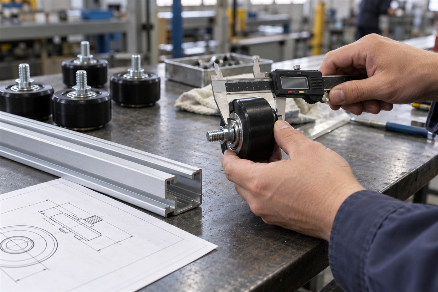
- Define the mating geometry. Provide the track, rail, cable, shaft or housing cross-section. Confirm the roller’s contact path, groove or crown, mounting axis and clearances. A photo helps explain the assembly, but a section drawing, sample or measured interface is more useful for design approval.
- Select the bearing and wheel together. Bearing size is only one input. The bearing arrangement must suit the load and speed; the outer wheel must suit the track, wear conditions, noise needs and manufacturing route. Seals, shields, internal clearance and lubricant should be confirmed against the environment and supplier data.
- Choose a manufacturable construction. Possible routes include using a standard bearing with a separately made wheel, moulding or coating the outer body around a bearing, machining a prototype, and assembling a bearing with a wheel and metal hardware. Each route has different tooling, fit, volume and change-control implications. The supplier should explain which route is proposed for the specific drawing.
- Control the interfaces and assembly. Decide how the bearing is located and retained, how press-fit or moulding forces are controlled, and how the axle or bracket locates the assembly. Do not let a production process change bearing clearance or damage seals without detecting it.
- Approve samples in the installed system. Check critical dimensions and movement on the actual or representative track and mounting structure. Review noise, alignment, rotation, retention and any application-specific test criteria. A loose sample on a desk cannot validate the complete mechanism.
- Release a controlled production specification. Approve the drawing revision, material and bearing references, assembly method, inspection points, packaging and change-notification rules. Use the same controlled revision for quotation, sample approval and repeat production.
How should the bearing be selected for an integrated roller?
Select the bearing from actual operating conditions, then verify that the roller and mounting preserve those conditions. Start with the load direction and distribution, rotation speed, duty cycle, contamination, lubrication, temperature, misalignment and mounting method. A bearing’s bore, outside diameter and width identify an envelope; they do not establish suitability by themselves.
ISO 281 describes calculation methods for rolling-bearing dynamic load ratings and rating life. That calculation is a bearing-level engineering tool; it does not guarantee the life of a complete roller assembly or account for every real mounting and track condition. SKF’s technical explanation also discusses how lubrication and contamination influence bearing-life calculations. In an OEM assembly, I treat a calculated bearing rating as one input and validate the roller, wheel material, fit and installed track separately.
Likewise, bearing dimensional tolerances should not be confused with the tolerance of a moulded or machined wheel. ISO 492:2023 specifies dimensional and geometrical characteristics and tolerance values for radial rolling bearings. The OEM drawing still needs to define the functional wheel and assembly interfaces around that bearing.
If the bearing is moulded into or tightly fitted inside a polymer wheel, include the fit and assembly method in the design review. The goal is secure retention without distorting the bearing or compromising its running behavior. The acceptable method depends on the bearing, wheel material, geometry and process; it should be confirmed by the supplier and validated on samples.
Which manufacturing route should an OEM use?
The route should match design maturity, volume, geometry and change risk. A low-volume prototype and a stable high-volume component may need different manufacturing decisions.
| Route | Potential advantage | Trade-off to review |
|---|---|---|
| Standard bearing plus separate machined wheel | Useful for prototypes or low quantities when geometry may change | More assembly steps and higher unit machining cost may apply |
| Injection-moulded wheel with bearing integration | Can suit repeat production and complex polymer profiles | Tooling, material grade, shrinkage, bearing location and process control need approval |
| Coated bearing roller | Can provide a resilient or higher-friction running surface for a defined interface | Coating adhesion, thickness, geometry and wear behavior need application validation |
| Bearing, wheel and hardware supplied as an assembly | Reduces buyer-side component coordination and handling | Scope, traceability, replacement strategy and approved assembly checks must be explicit |
These are general routes, not a claim that every design can use every process. HUNE’s material and process selection page describes coordinated bearing, roller outer-body, metal hardware, surface-treatment and assembly work for custom bearing roller projects. The practical question is whether the proposed route fits the specific assembly and production plan.
What should be verified before mass production?
Approve the complete moving interface, not just the bearing or a single component dimension. A useful sample-approval plan should define what will be checked and what decision each check supports.
- Drawing review: Are the bearing seat, running profile, mounting axis, overall width and track interface dimensioned from clear datums?
- Material confirmation: Is the exact polymer, coating, metal and bearing configuration named or otherwise controlled? Generic labels such as “nylon” may not define the grade.
- Assembly inspection: Is the bearing seated and retained as intended? Are seals, shields, spacers, threads and brackets undamaged?
- Installed fit: Does the roller track smoothly through the actual profile and mounting geometry? Is contact occurring where the design intends?
- Application test: Does the assembly meet the buyer’s defined load, speed, environmental and duty requirements in the representative mechanism?
- Production repeatability: Are inspection method, sampling plan, lot identification, packaging and change-control responsibility agreed?
The correct acceptance limits depend on the product drawing and buyer requirements. I would not approve an undefined statement such as “smooth movement” as the only acceptance criterion; describe the installation, motion and checks that make the requirement repeatable.
What should buyers send for a one-stop bearing roller RFQ?
Give the supplier enough information to quote the assembly and identify unresolved engineering questions. A useful RFQ package includes:
- 2D drawing, 3D CAD file or physical sample, with revision number.
- Track, rail, cable or mating-shaft section and installation orientation.
- Critical running dimensions, mounting dimensions, datums and required tolerances.
- Expected load direction and distribution, speed, duty cycle and impact conditions.
- Environment, including dust, moisture, chemicals, temperature and corrosion exposure.
- Required bearing reference or permission to propose an alternative, plus seal/shield preference where known.
- Wheel material, color, surface, noise or wear priorities, if specified.
- Annual demand, sample quantity, target production timing and packaging requirements.
- Required inspection records, declarations, tests or customer approval steps.
- Known failure history or design constraints, clearly separated from confirmed requirements.
If the design is incomplete, say what is fixed and what can be changed. For example, the track may be fixed while the wheel profile and mounting hardware remain open to optimization. That helps the supplier propose options without silently changing a critical interface.
HUNE’s bearing-integrated roller range includes multiple wheel profiles and mounting structures. A POM bearing roller with a threaded stud is one example of an assembly where wheel, bearing and mounting feature are designed together; the actual fit and material still need to match the buyer’s track and operating conditions.
Frequently Asked Questions
Is a one-stop bearing supplier the same as a bearing manufacturer?
No. “One-stop” describes the scope and coordination of sourcing or production; it does not prove that every component is manufactured in one factory. Ask which components are made in-house, which are sourced, who owns assembly and inspection, and how traceability and change control are handled.
Does a larger bearing automatically make a roller carry more load?
No. The complete assembly carries the application load. Bearing capacity, wheel material and section, bearing-seat support, axle, bracket, track contact, load direction and mounting all matter. Request application-specific selection and validate the installed assembly rather than selecting by bearing size alone.
Can one supplier coordinate bearing, plastic wheel and metal bracket production?
Yes, if the supplier’s defined OEM scope includes those parts and the buyer approves the design, sources, manufacturing route and quality controls. Confirm the scope in writing; do not infer it from the phrase “one-stop service.”
What is the difference between a bearing roller and a complete roller assembly?
A bearing roller often means a wheel with a bearing integrated into its center. A complete assembly may also include a stud or axle, spacer, retaining feature, bracket or housing. The RFQ should show which items the supplier must provide and how they mount in the final machine.
When does a custom bearing roller make sense?
Custom development is useful when a standard part does not match the track profile, installation envelope, mounting method, material, environment or assembly requirements. If a standard roller already fits the functional interface and production needs, a custom design may add tooling and approval work without a clear benefit.
Practical recommendation
A one-stop solution works when the bearing, wheel, mounting hardware and inspection plan are controlled as one approved assembly. Start with the application and mating geometry, assign each critical interface, choose a manufacturable route, and validate samples in the real mechanism before releasing repeat production.


