

Bearing bore and outside diameter affect two different interfaces in a plastic roller. The bearing bore fits the axle, stud or shoulder bolt and therefore influences inner-ring location, mounting clearance and load transfer. The bearing outside diameter fits the plastic wheel hub and influences bearing retention, plastic wall thickness, mould design and wheel concentricity. Neither dimension alone determines roller performance.
I normally review the bearing width, wheel running diameter, minimum plastic section, shaft support, load direction, speed, duty cycle and environment at the same time. A larger bore may require a stronger or larger axle but leave less space inside a compact bearing. A larger bearing outside diameter may offer another bearing capacity option, yet it also removes plastic from a fixed-size wheel. The correct choice is the combination that preserves the whole load path and can be manufactured consistently.
What Do Bearing Bore and Outside Diameter Mean?
The bore is the opening through the inner ring; the outside diameter is the cylindrical surface of the outer ring.
Rolling-bearing drawings commonly use:
- d for bearing bore diameter;
- D for bearing outside diameter; and
- B for bearing width in a radial bearing.
SKF illustrates these terms in its bearing basics and shaft-bearing-housing terminology. ISO 15:2017 defines a general plan of preferred boundary dimensions for radial bearings. These references help engineers communicate the bearing envelope, but they do not select the finished plastic roller or prescribe one fit for every application.
For a plastic-coated bearing roller, three outside dimensions must remain separate:
- the bearing outside diameter;
- the plastic wheel's maximum outside diameter; and
- the functional running diameter where the wheel actually contacts the rail, belt, cable or guide.
On a flat wheel, the maximum and running diameters may be similar. On a U-groove, V-groove or crowned wheel, the actual contact diameter can be smaller than the flange or maximum diameter. This distinction affects installed height, travel ratio and clearance.
| Dimension | Mating feature | Main function | Common mistake |
|---|---|---|---|
| Bearing bore, d | Axle, stud or shoulder bolt | Locates and supports the inner ring | Treating the nominal bore as a complete shaft-fit specification |
| Bearing outside diameter, D | Plastic hub or bearing seat | Locates and retains the outer ring | Selecting D without checking remaining plastic wall |
| Bearing width, B | Shoulders, spacers and wheel width | Controls axial stack and support | Ignoring side clearance or clamping the wrong ring |
| Wheel running diameter | Track, rail, cable or mating surface | Sets contact height and movement ratio | Using the largest flange diameter in the motion calculation |
How Do Bore and Outside Diameter Control Different Interfaces?
The bore controls the metal mounting interface, while the outside diameter controls the bearing-to-plastic interface. Both must be dimensioned from functional datums.
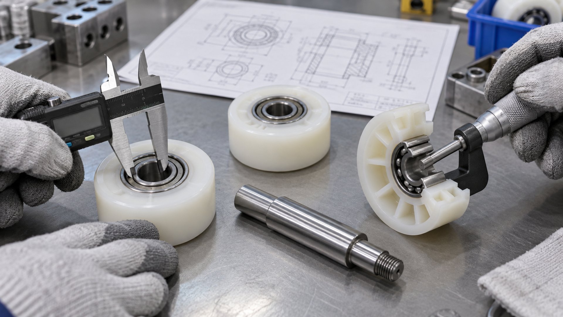 The bore is checked against the axle interface, while the bearing outside diameter and plastic seat are evaluated as a separate fit.
The bearing bore does not contact the plastic wheel. It normally contacts an axle, pin, threaded stud or shoulder bolt. The resulting fit must locate the inner ring, allow assembly and resist unwanted movement under the intended load. The correct fit depends on which ring rotates relative to the load, the load level and direction, temperature, shaft construction and service conditions.
The bearing outside diameter contacts the wheel seat. In an overmoulded construction, plastic is formed around the bearing. In a separately moulded construction, the bearing may be pressed into a hub and retained by interference, shoulders, washers, snap features or another approved method. Each route creates different dimensional and stress questions.
I would not place one general “tight fit” instruction on the whole roller. Excessive interference at the outer ring can distort the bearing or alter its internal running condition. Too little retention can allow the bearing to move, creep or become loose in the wheel. The buyer should define the functional result and agree on the seat, assembly route and inspection method with the supplier.
Our guide to bearing clearance and its effect on roller assemblies explains why internal bearing clearance and mounting fit are related but are not the same specification.
How Does Bearing Bore Affect the Axle and Mounting System?
A bearing bore sets the basic axle diameter, but the axle's shoulders, support length, fastening method and finish determine whether that interface works.
A larger bore can permit a larger axle, which may help stiffness or fastening in some assemblies. It does not automatically create a stronger roller. Changing the bore can also change the bearing series, ring cross-section, available rolling-element space and outside diameter. The supplier must evaluate the actual bearing designation rather than treating bore size as an isolated hole dimension.
The bore decision affects:
- axle or stud diameter and tolerance;
- shaft shoulder diameter and fillet clearance;
- unsupported span between brackets;
- thread size and usable shoulder length;
- spacer and washer inside diameters;
- assembly tool access;
- inner-ring clamping or floating arrangement; and
- replacement compatibility.
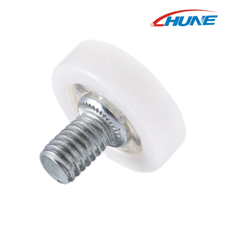
For a threaded-stud roller, the bearing bore may be hidden by a custom axle or swaged connection. HUNE's POM bearing roller with an integrated threaded stud shows this compact architecture. The visible thread is a mounting feature; its diameter should not be assumed to equal the bearing bore.
What if the shaft is too small or too large?
A shaft that does not provide the intended location may allow relative motion, misalignment or impact at the inner ring. A fit that is too tight for the selected bearing and assembly method may make installation difficult or change the bearing's operating condition. The result also depends on whether the inner ring is clamped against a shoulder, allowed to float or carried on a riveted pin.
I first ask which member is intended to rotate: the wheel and bearing outer ring around a fixed axle, or the entire wheel-and-axle unit inside another support. That answer defines which interfaces require retention and which require freedom of movement.
How Does Bearing Outside Diameter Affect the Plastic Wheel?
For a fixed wheel diameter, increasing the bearing outside diameter reduces the radial space available for plastic, groove geometry and local reinforcement.
For a simple concentric flat wheel, a useful first geometry check is:
nominal radial plastic section = (wheel outside diameter − bearing outside diameter) ÷ 2
This is only an initial envelope calculation. The true minimum plastic section may be smaller because of a groove, crown, flange, chamfer, moulding feature or bearing-retention detail. Load does not pass uniformly through an ideal ring of plastic; it concentrates near the track contact and bearing seat.
The bearing outside diameter influences:
- minimum plastic thickness around the bearing;
- space available for U-, V-, flat or crowned running profiles;
- insert support and positioning in the mould;
- cooling and shrinkage around the metal insert;
- risk of sink, voids, flash or local deformation;
- feasibility of press fitting;
- wheel stiffness and contact deformation; and
- the datum used to control tread runout.
A larger D may be useful when the selected bearing family suits the load and operating requirement. However, if the wheel OD cannot grow, the remaining plastic may become too thin for stable moulding or the required track profile. A smaller D leaves more plastic, but the associated bearing construction must still meet the speed, load, environment and life requirement. There is no universal best ratio.
Does a Larger Bearing Always Improve a Plastic Roller?
No. A larger bearing changes the load-carrying component and the plastic geometry at the same time.
Engineers sometimes compare catalogue dynamic load ratings and choose the largest bearing that fits inside the wheel. That can overlook the weakest or least stable part of the assembly. The limiting factor may instead be:
- the axle bending between supports;
- a thin plastic section above the bearing;
- local stress at a groove contact;
- inadequate outer-ring retention;
- bracket deformation;
- track damage or excessive contact pressure;
- contamination entering the bearing; or
- misalignment between two roller positions.
Increasing bearing precision also does not automatically correct wheel moulding error, axle runout or bracket misalignment. The related article Do Higher-Precision Bearings Always Improve Roller Performance? separates bearing accuracy from the accuracy of the complete roller.
I choose the bearing only after the load path and available wheel envelope are known. Then I compare realistic bearing arrangements, plastic sections and manufacturing routes instead of ranking bearings by outside diameter alone.
How Does the Complete Roller System Carry Load?
The bore and outside diameter matter because they sit in the middle of a complete load path from the supported object to the track.
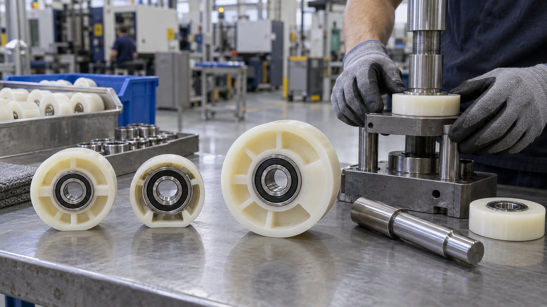 A plastic roller with an integrated bearing must be evaluated together with its stud, wheel profile and mating track.
A typical load path is:
moving panel or machine carriage → bracket → axle or stud → bearing inner ring → rolling elements → bearing outer ring → plastic wheel → track
The direction can reverse or include side load depending on the application. A guide wheel that only controls lateral position does not have the same duty as a roller supporting a door, drawer or machine carriage. Likewise, a cable pulley produces a different contact pattern from a flat roller on a rail.
The U-groove plastic bearing pulley range illustrates how bearing dimensions, plastic outside geometry and groove proportions form one unit. Groove radius and depth must match the cord, cable or round rail; they cannot be chosen from bearing D alone. Buyers comparing broader structures can also review the sliding rollers with bearing category.
How Does Manufacturing Route Change the Bearing Seat?
Overmoulding and press fitting can both produce a plastic roller, but they do not use the bearing outside diameter in the same way.
 Bearing OD, plastic wall and assembly method must be designed together before tooling is approved.
Bearing overmoulded into the wheel
The bearing is positioned as an insert and plastic is moulded around it. The mould must locate the insert, prevent harmful movement during filling and control the finished running profile relative to the bearing axis. The design must consider resin flow, shrinkage, cooling, bearing protection and the effect of moulding conditions on the insert.
This route can reduce a separate bearing-installation step, but the finished seat cannot be evaluated only from the nominal cavity dimension. The actual material grade, tool design and process establish the final condition.
Separately moulded wheel with a fitted bearing
The wheel is moulded first and the bearing is installed afterward. This can simplify bearing protection during moulding and permit separate inventory, but the bore of the plastic hub and the bearing OD need a controlled assembly strategy.
The Celanese Celcon POM design guide notes that a straight interference press fit can create high strain in a plastic part and presents alternative lower-stress concepts. This does not supply a universal roller fit. It supports the engineering point that metal-to-plastic interference must be designed for the actual resin, hub geometry and service condition.
Moulding plus secondary machining
Machining may be used for a critical seat or running profile when the project requires it and the construction allows it. It adds operations, inspection and cost, and it does not remove the need to control moulded datums and material stability. HUNE's OEM roller development process shows how bearing preparation, injection moulding, hardware processing and final assembly are coordinated against one approved structure.
Which Dimensions Should Be Controlled on the Drawing?
Control the interfaces and relationships that govern rotation; avoid tightening every cosmetic dimension.
| Drawing control | Why it matters | Suggested reference or datum |
|---|---|---|
| Bearing designation or approved boundary dimensions | Defines d, D, B and closure arrangement | Supplier bearing data or approved specification |
| Axle seat diameter and length | Controls inner-ring location and support | Shaft axis and shoulder |
| Bearing seat construction | Controls outer-ring retention | Bearing axis or qualified mould datum |
| Wheel running diameter | Sets installed height and motion | Bearing bore or bearing axis |
| Tread or groove runout | Controls cyclic motion and noise | Bearing axis after assembly |
| Wheel width and axial stack | Controls side clearance | Functional side face or bracket datum |
| Minimum plastic section | Preserves material around the bearing and profile | Section through critical load path |
| Shoulder and chamfer clearances | Prevents unintended contact | Mating bearing corner geometry |
| Bracket position | Aligns wheel with the track | Mounting holes or frame datum |
The drawing should also state the plastic grade or approved material specification, bearing closure, axle material and finish, retention method, inspection condition and revision level. If the bearing is overmoulded, the drawing should distinguish bearing dimensions from final wheel dimensions.
I prefer to define tread runout relative to the assembled bearing axis instead of only controlling the plastic OD relative to a mould surface. That relationship is closer to what the track experiences during rotation.
How Should an OEM Validate the Size Combination?
Approve the bearing, plastic geometry and installed roller as a sequence; one loose sample cannot validate repeat production.
- Requirement review: Confirm load direction, number of rollers, speed, duty cycle, environment, noise target and available installation envelope.
- Interface review: Check the axle, bearing bore, bearing OD, wheel profile, bracket and track as one dimensional chain.
- Geometry sample: Confirm assembly, track contact, clearances and accessibility before committing to final tooling where possible.
- Tooling sample: Inspect the bearing position, wheel diameter, profile, width, appearance and runout from the actual production route.
- Installed test: Run the roller in the real or representative track under the application's load and alignment conditions.
- Pilot production: Check variation across multiple parts and assemblies, including bearing retention and free rotation.
- Repeat-production control: Agree on critical dimensions, gauges, sampling and change control.
The validation should look for binding, excessive play, bearing movement in the hub, plastic damage, irregular contact, noise and changes after cycling. Acceptance values must come from the customer's system requirements or an agreed test plan rather than from an invented universal roller standard.
What Should a Buyer Send the Roller Supplier?
A useful enquiry defines the complete interface, not only “bearing bore × wheel OD.”
Send the following information:
- application and function: support, guide, tension or transmission;
- 2D drawing, 3D model or physical sample;
- bearing designation or required d × D × B dimensions;
- axle or stud drawing, including shoulders, threads and fastening;
- finished wheel OD, width and running profile;
- mating track, rail, cable or belt cross-section;
- load direction, estimated load distribution and number of rollers;
- speed, travel frequency and expected duty cycle;
- temperature, moisture, dust, chemicals or outdoor exposure;
- preferred plastic grade, bearing material and shield or seal arrangement;
- critical tolerances and how they will be measured;
- prototype, first-order and annual quantity; and
- installed validation and packaging requirements.
If an existing roller is being replaced, include both the worn sample and an unworn mating-track section when available. A worn outside diameter can mislead reverse engineering, while a bearing marking alone may not reveal the approved fit or axle construction.
Discuss a Custom Plastic Roller with HUNE
HUNE develops plastic-coated bearing rollers together with their bearings, shafts, studs, brackets and mating geometry for OEM projects.
We can review an existing structure or a new roller concept, compare bearing and wheel envelopes, and assess whether direct overmoulding, a separately moulded wheel or secondary machining is appropriate. The review begins with the functional interface and expected production volume; it does not begin by forcing every project into one standard wheel.
For an engineering review, send the bearing size, shaft or stud drawing, wheel profile, track section, load direction, operating conditions and expected quantity through the HUNE enquiry page. These details allow the bearing bore, bearing outside diameter and plastic geometry to be assessed as one assembly.
Frequently Asked Questions
Is bearing bore the same as shaft diameter?
The nominal values may correspond, but they are not a complete fit specification. The bearing bore has its own dimensional tolerance, and the shaft seat needs a tolerance, surface condition, geometry and mounting arrangement appropriate to the load and ring behavior. A shoulder bolt may also include a threaded portion smaller than its bearing seat. Specify the bearing designation and the functional shaft seat instead of ordering from one nominal number.
Can I use the same bearing bore with a different outside diameter?
Sometimes. Different bearing series can share a bore while using different outside diameters and widths. Changing series changes the envelope and may change capacity, speed capability, closure options and space for plastic. The wheel hub, minimum wall, mould insert and axial stack must all be checked. Treat the alternative as a new assembly configuration and validate it in the actual roller system.
How much plastic should remain around the bearing?
There is no universal minimum wall that applies to every roller. The required section depends on plastic grade, wheel diameter, groove depth, load path, moulding route, retention method, environment and acceptance criteria. Use the radial section calculation only as an early packaging check, then evaluate the thinnest real cross-section and validate production samples under representative service conditions.
Should the plastic wheel rotate on the bearing outer ring?
In a common plastic-coated bearing roller, the plastic wheel is fixed to the bearing outer ring, and both rotate together around an inner ring located on the axle. Other constructions exist, including rollers with different retention or axle arrangements. The drawing must identify which parts rotate, which ring is retained and where axial clamping is applied. Do not infer the load path from appearance alone.
Final Engineering Recommendation
Select bearing bore and outside diameter as part of the roller's complete dimensional chain. The bore must suit the axle, shoulders and retention method. The outside diameter must suit the plastic seat, minimum wall, moulding process and running profile. Bearing width, wheel diameter, track contact, runout and bracket alignment complete the decision.
Before approving tooling, compare at least the bearing–shaft interface, bearing–plastic interface and wheel–track interface on one assembly drawing. Then validate samples in the intended track under representative load and duty. For a supplier review, send HUNE the bearing designation, axle geometry, wheel and track sections, critical datums, operating conditions and expected quantity so the design can be assessed before production.


