

6200-series bearing dimensions define the bearing's basic envelope: bore diameter d, outside diameter D and width B. For example, a standard 6200 bearing is 10 × 30 × 9 mm, while a 6202 is 15 × 35 × 11 mm. These dimensions set the shaft size, bearing seat and minimum axial space available inside a roller. They do not define the finished plastic wheel diameter, groove profile or load capacity of the complete roller.
I do not select a plastic roller by replacing the last two digits until the bore fits. Moving from 6200 to 6201 or 6202 changes all three boundary dimensions, so the shaft, remaining plastic wall, mould insert, wheel width, bracket and track position may also change. The bearing suffix, internal clearance, closure, material, lubrication and manufacturer data must then be confirmed separately. Roller design starts with the complete load path, not the bearing number alone.
How Is a 6200-Series Bearing Number Read?
In a basic designation such as 6202, “6” identifies a deep-groove ball bearing, “2” identifies the dimension series, and “02” is the bore code.
SKF's bearing designation guidance explains that a basic designation identifies bearing type, ISO dimension series and bore code. The same source lists the special small-bore codes:
- 00 = 10 mm bore
- 01 = 12 mm bore
- 02 = 15 mm bore
- 03 = 17 mm bore
From code 04 upward in the normal coded range, multiplying the final two digits by five gives the nominal bore in millimetres. Therefore 6204 has a 20 mm bore, 6205 has a 25 mm bore and 6206 has a 30 mm bore.
This rule is useful, but it should not be extended blindly to every bearing designation. Special bores, small bearings and other bearing types can use different presentation rules. I verify the exact manufacturer designation and product table before releasing a roller drawing.
ISO 15:2017 specifies preferred boundary dimensions for radial bearings. It provides the dimensional framework behind standard interchangeability. It does not say that any bearing with the same d × D × B has the same internal design, capacity, closure or suitability for an overmoulded wheel.
What Are the Common 6200-Series Bearing Dimensions?
The series grows in bore, outside diameter and width; changing one designation normally changes the whole bearing envelope.
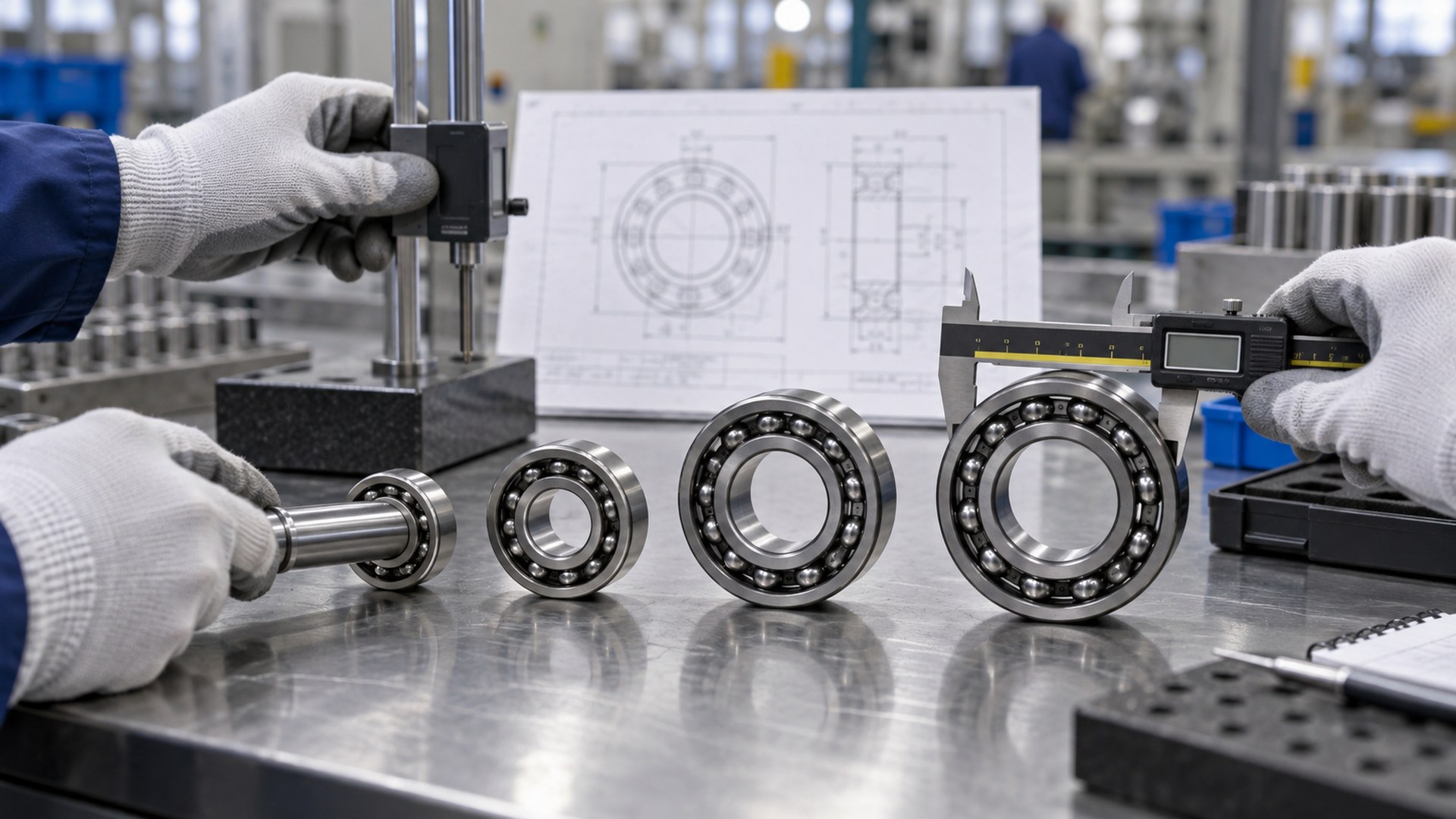 Boundary dimensions should be confirmed from the approved bearing supplier before the roller, shaft and mould are released.
The following metric boundary dimensions are listed in SKF and NSK technical catalogues for common 62-series deep-groove ball bearings:
| Basic designation | Bore d (mm) | Outside diameter D (mm) | Width B (mm) | Immediate roller-design implication |
|---|---|---|---|---|
| 6200 | 10 | 30 | 9 | Requires a 10 mm nominal shaft interface and at least a 30 mm bearing-seat envelope |
| 6201 | 12 | 32 | 10 | Increases shaft, hub and axial-stack requirements |
| 6202 | 15 | 35 | 11 | Removes more plastic from a fixed wheel OD than 6200 or 6201 |
| 6203 | 17 | 40 | 12 | Requires a larger hub and wider wheel or controlled bearing projection |
| 6204 | 20 | 47 | 14 | Becomes difficult to package in compact plastic rollers without increasing wheel size |
| 6205 | 25 | 52 | 15 | Requires a substantial axle and plastic-wheel envelope |
| 6206 | 30 | 62 | 16 | Suits a much larger assembly than the “6200” model itself |
| 6207 | 35 | 72 | 17 | Bracket, track and handling scale must grow with the bearing |
| 6208 | 40 | 80 | 18 | Requires review as a larger mechanical roller system, not a small hardware wheel |
SKF's deep-groove ball-bearing catalogue table and NSK's industrial bearing dimension tables support these d × D × B values. Always use the current approved supplier drawing for purchasing and production control.
The table should not be read as a load ranking for finished rollers. As the designation grows, the bearing geometry changes, but the roller may still be limited by its axle support, plastic section, bracket, track or alignment.
How Do 6200-Series Dimensions Change a Plastic Roller?
The bore sets the shaft interface, the outside diameter consumes the plastic hub envelope, and the width affects the wheel and bracket stack.
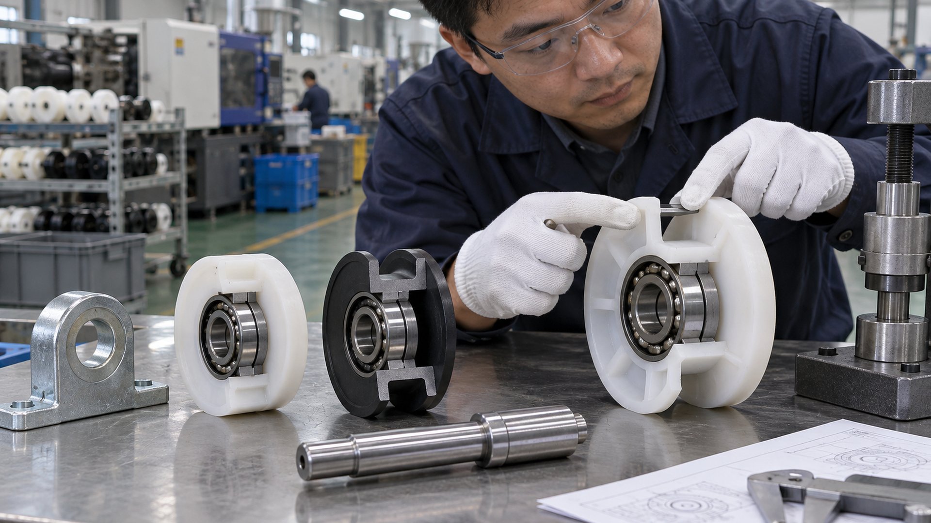 A larger 62-series bearing changes the shaft, plastic wall, profile and axial package together.
Bore diameter d: shaft and stud interface
The bearing bore controls the nominal size of the axle seat, stud shoulder or shaft. It also influences:
- shaft stiffness and unsupported span;
- shoulder and fillet geometry;
- thread size available beyond the bearing seat;
- spacer and washer inside diameters;
- assembly method and tool access; and
- compatibility with the bracket or machine frame.
A 6202 does not simply provide “a little more bearing” than a 6201. It changes the nominal shaft interface from 12 mm to 15 mm. If the existing bracket accepts only a 12 mm shoulder bolt, the change may require a new axle and mounting structure.
Outside diameter D: plastic hub and profile envelope
The bearing OD defines the minimum metal envelope around which the plastic wheel must be designed. For a concentric flat wheel, an early packaging check is:
nominal radial plastic section = (finished wheel OD − bearing OD) ÷ 2
This is not a universal wall-thickness rule. A groove, flange, crown, chamfer, mould insert or retention feature may create a thinner local section. The real design must be checked at the track contact and through the load path.
If a roller is fixed at 45 mm finished OD, a 30 mm bearing and a 40 mm bearing leave very different nominal radial space for plastic. The larger bearing may suit one mechanical requirement but leave too little room for a U-groove or robust tread. Increasing D can therefore force a larger finished wheel.
Width B: wheel, spacer and bracket stack
Bearing width controls more than the minimum wheel width. The assembly may also need:
- plastic coverage or side faces;
- axial shoulders or retaining washers;
- seal clearance;
- bracket clearance;
- a spacer between paired bearings; and
- room for fastening and adjustment.
A wheel can be wider than the bearing, or the bearing can project from one or both faces. Both arrangements can work when the axial retention and track alignment are defined. I do not assume the wheel should finish flush with B.
Why Does the “62” Dimension Series Matter?
Bearings with the same bore can have different outside diameters and widths because they belong to different dimension series.
For a 15 mm nominal bore, common deep-groove bearing envelopes include:
| Basic designation | d (mm) | D (mm) | B (mm) | Packaging effect in a plastic roller |
|---|---|---|---|---|
| 6002 | 15 | 32 | 9 | Leaves more radial and axial space in a fixed wheel envelope |
| 6202 | 15 | 35 | Uses a larger OD and greater width than 6002 | |
| 6302 | 15 | 42 | Requires substantially more hub and axial space |
The NSK dimension table confirms these boundary dimensions. The comparison does not prove that one series is better. The internal geometry, catalogue ratings, speed capability, availability, closures and price must be evaluated for the exact product. The plastic wheel must also retain enough material for its profile and manufacturing route.
I normally compare several complete concepts: bearing, shaft, plastic wheel and track. Choosing a thinner series may solve packaging but fail another requirement. Choosing a larger series may consume the wheel wall without improving the actual system if the track or bracket remains the limiting component.
Do 2RS, ZZ, C3 and Other Suffixes Change the Dimensions?
Many suffixes describe closures, clearance or internal features rather than the basic d × D × B envelope, but suffix meanings and details must be checked with the manufacturer.
Common suffix categories can indicate:
- one or two metal shields;
- one or two contact or low-friction seals;
- internal radial clearance;
- cage or internal design variation;
- material or corrosion-resistant execution;
- lubricant specification; or
- snap-ring features and other external modifications.
For many standard 6200, 6201 and 6202 shielded or sealed variants, the nominal boundary dimensions remain those of the basic designation. That does not make the variants functionally interchangeable in a roller. Seal contact can affect torque; shields and seals provide different contaminant protection; clearance interacts with fit and temperature; and an external snap-ring feature can affect the hub design.
HUNE's guide to sealed and shielded bearing differences explains the closure decision. The article on bearing clearance in roller assemblies explains why C3 or another clearance suffix should not be treated as a general upgrade.
Do not approve a purchase description that says only “6202 bearing” when the application requires a specific closure, material, clearance or lubricant. Record the complete approved designation and supplier data.
How Does the Bearing Fit into the Complete Roller System?
The 6200-series bearing sits between the axle and plastic wheel; the finished roller still has to match its bracket and track.
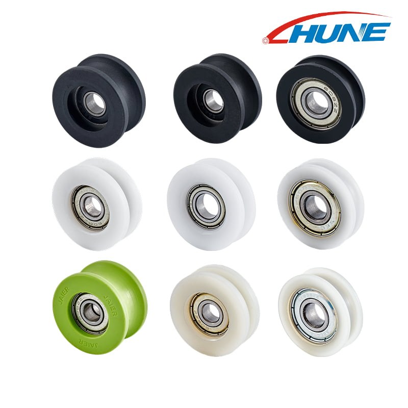 HUNE's U-groove range can use different bearing series, plastic materials and groove dimensions according to the approved roller design.
A typical load path is:
moving equipment, panel or cable → bracket or tension member → axle → bearing inner ring → rolling elements → outer ring → plastic wheel → track, rail or cable
Changing from 6201 to 6203 may alter every interface in this chain. The larger bore changes the axle. The larger D changes the bearing seat and available plastic. The greater B changes the axial stack. The larger finished wheel may change track height, wrap geometry or movement ratio.
The HUNE U-groove bearing pulley wheel range lists 6200, 6000 and 6900 series among configurable bearing options. The product page also makes the important system point: groove radius, width and depth must correspond to the cable, round rail or guided member. The bearing series cannot select that interface.
For other architectures, the sliding rollers with bearing category shows flat, grooved, flanged and stud-mounted structures. These examples should be compared by load path and mating geometry, not only by bearing code.
How Should the Bearing Be Retained in the Plastic Wheel?
The bearing OD is a standard boundary dimension, but the plastic seat and retention method are application-specific.
Typical constructions include:
- Direct overmoulding: Plastic is moulded around a prepared bearing insert. The mould locates the bearing and forms the wheel profile in one process.
- Separate moulding and press fitting: The wheel is moulded first, then the bearing is installed into a controlled seat.
- Moulding plus secondary machining: A critical seat or tread may be machined after moulding where the project justifies the extra operation.
- Mechanical retention: Shoulders, washers, snap features, spacers or fasteners retain the bearing according to the approved assembly.
An interference value that works in a metal housing should not be copied automatically into POM, nylon or another plastic. Resin grade, hub geometry, moulding shrinkage, moisture, temperature and service time can change the result. Excessive interference may distort the outer ring or overstress the hub; insufficient retention may allow movement.
HUNE's roller materials and manufacturing process page helps buyers compare plastic, bearing and hardware choices. The OEM development process shows why bearing preparation, insert positioning, moulding, assembly and final movement checks are controlled as one project.
Which Dimensions Belong on the Roller Drawing?
The drawing should state the complete bearing designation and control the finished roller from the bearing axis.
| Drawing item | Why it matters | Practical control |
|---|---|---|
| Complete bearing designation | Fixes basic size plus required suffixes | Approved manufacturer data or project specification |
| Bearing d × D × B | Defines the metal envelope | Reference dimensions linked to the designation |
| Axle seat and shoulders | Locates the inner ring | Diameter, length, fillet and datum axis |
| Plastic bearing seat | Controls outer-ring retention | Process-specific dimension and inspection condition |
| Finished running diameter | Controls installed height and travel | Measured relative to bearing axis |
| Groove or tread profile | Controls track, cable or rail contact | Radius, angle, width, depth and functional datum |
| Wheel and assembly width | Controls bracket clearance | Side-face or bracket datum |
| Tread runout | Controls cyclic force and motion | Relative to the assembled bearing axis |
| Axial retention | Prevents unintended movement | Shoulder, washer, spacer or other approved feature |
Cosmetic radii, non-contact surfaces and colour dimensions should not receive tight tolerances unless they serve a function. Unnecessary tolerances increase tooling, machining and inspection cost without improving movement.
How Should an OEM Validate a 6200-Series Roller?
Catalogue dimensions start the design; installed testing approves the roller.
I use a staged review:
- Confirm the requirement. Define load direction, roller count, speed, duty, environment, noise, track and installation envelope.
- Select candidate bearings. Compare full designations, manufacturer data, availability and boundary dimensions.
- Close the dimensional chain. Check shaft, d, D, B, plastic wall, wheel profile, bracket and track position.
- Review the production route. Confirm overmoulding, press fitting, secondary machining and retention details.
- Inspect tooling samples. Check bearing position, wheel dimensions, runout, free rotation, surface condition and retention.
- Test the installed assembly. Use the intended track and representative load, alignment and cycle conditions.
- Approve repeat-production controls. Agree on critical dimensions, gauges, sampling, traceability and change control.
One hand-assembled prototype does not establish moulding consistency or long-term performance. Likewise, a bearing catalogue rating does not account for a thin plastic tread, a flexible bracket or a misaligned track.
What Should a Buyer Send the Supplier?
Send enough information to verify the bearing, wheel and mating system together.
For an OEM quotation or design review, provide:
- application and roller function;
- complete preferred bearing designation and manufacturer, if fixed;
- acceptable alternative series or sourcing constraints;
- 2D drawing, 3D model or physical sample;
- axle, stud, shoulder and fastening geometry;
- finished wheel OD, width and running profile;
- mating track, cable, rail or belt section;
- load direction, roller quantity and estimated load distribution;
- speed, travel length and duty cycle;
- temperature, moisture, dust and chemical exposure;
- plastic material requirement and colour;
- critical dimensions, datums and inspection method;
- prototype and expected annual quantity; and
- installed test or approval requirements.
If the request is based on an existing bearing marking, include photographs of both faces and measure the actual d × D × B. Counterfeit, worn, special-bore or manufacturer-specific variants can make a partial code unreliable.
Discuss a 6200-Series Plastic Roller with HUNE
HUNE can review the bearing, plastic wheel, shaft, bracket and track as one OEM assembly.
We manufacture and coordinate plastic-coated bearing rollers, pulley wheels, shafts, studs and related hardware. For a 6200-series project, we can compare the available wheel envelope with the selected bearing D and B, review the axle against d, and evaluate an existing mould, secondary machining or new tooling route.
Send the bearing designation, wheel and track drawings, axle construction, load direction, operating conditions and expected quantity through the HUNE contact page. These details allow a useful engineering review before tooling or mass production.
Frequently Asked Questions
Is a 6200 bearing 20 mm inside diameter?
No. In the standard designation system, the final code 00 corresponds to a 10 mm bore. A basic 6200 deep-groove ball bearing has nominal boundary dimensions of 10 × 30 × 9 mm. The 20 mm bore appears at code 04, so a 6204 has a 20 mm nominal bore. Always verify the full designation and manufacturer table.
Do 6200 and 6201 bearings fit the same shaft?
No. A 6200 has a 10 mm nominal bore, while a 6201 has a 12 mm nominal bore. Their outside diameters and widths also differ: 30 × 9 mm versus 32 × 10 mm after the bore value. Changing between them normally requires review of the axle, wheel hub, axial stack, bracket and tooling.
Can a 6002 replace a 6202 in a plastic roller?
They share a 15 mm nominal bore, but their outside diameter and width differ. A 6002 is 15 × 32 × 9 mm, while a 6202 is 15 × 35 × 11 mm. The plastic seat and axial retention therefore differ, and performance data may also differ. Treat the substitution as a design change and validate the complete roller.
Does 6202-2RS have the same size as 6202-ZZ?
Common standard versions generally retain the basic 15 × 35 × 11 mm boundary envelope, but the closures and manufacturer suffixes differ. Seal contact, contaminant protection, grease, internal clearance and torque can affect roller behavior. Confirm the exact supplier drawings and do not use the matching envelope as proof of functional equivalence.
Which 6200-series bearing is best for a plastic roller?
There is no single best designation. The choice depends on shaft size, available wheel OD and width, minimum plastic section, load direction, speed, duty, environment, closure, alignment and supply requirements. Start with the complete roller and track geometry, compare candidate bearing data, then validate the manufactured assembly under representative conditions.
Final Engineering Recommendation
Use 6200-series bearing dimensions to define the roller envelope, not to finish the design. The code establishes d, D and B: the shaft interface, bearing-seat envelope and axial space. The plastic wheel still needs enough material for its tread or groove, while the axle, bracket and track must preserve the intended load path and alignment.
Before approving tooling, record the complete bearing designation, close the shaft–bearing–wheel–track dimensional chain, and inspect runout from the assembled bearing axis. Then test production-intent samples in the real system. For a supplier review, send HUNE the bearing data, axle and wheel drawings, mating track, operating conditions, validation plan and expected volume.


