

A cable pulley bearing in fitness equipment lets a grooved wheel rotate around an axle while the cable changes direction or moves a resistance mechanism. In a common assembly, the bearing inner ring is located on the axle, the outer ring turns with the pulley, and the rolling elements carry force between them. Cable tension enters through both sides of the groove, combines into a resultant load, and then passes through the wheel hub, bearing, axle, bracket and machine frame.
That is why the selected weight alone does not define the bearing load. Pulley position, cable direction change, moving-pulley ratio, acceleration, alignment and friction all affect what the bearing actually sees. A fixed pulley mainly redirects the cable; a moving pulley can also change handle travel and mechanical advantage. I therefore evaluate the entire cable route before choosing or approving the pulley.
What Happens Inside a Fitness Equipment Bearing Pulley?
The pulley guides the cable, while the bearing transfers the resulting force into a stationary support with low rotational resistance.
The load path is easier to understand when the parts are viewed in order:
Cable → groove → pulley body and hub → bearing outer ring → rolling elements → bearing inner ring → axle → bracket → machine frame
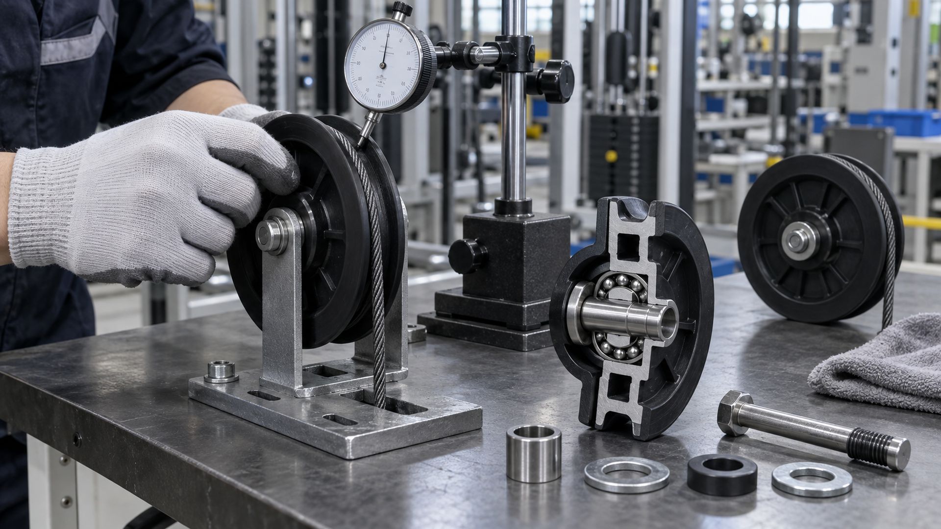
Many fitness pulleys use a moulded engineering-plastic wheel around a deep-groove ball bearing. The wheel rotates with the bearing outer ring. A bolt, shoulder axle or machined pin locates the inner ring between the bracket plates. Spacers or a controlled shoulder keep the rotating wheel from rubbing the bracket.
The bearing changes the interface from a wheel sliding directly on a pin to rolling contact inside the bearing. This reduces rotational resistance, but it does not make the pulley frictionless. Bearing seals, grease, cable flexing, wheel deformation and small alignment errors all contribute to the force that the user feels.
The assembly must also preserve the intended internal clearance. If a bracket clamps the inner ring unevenly, if a spacer is too short, or if the bolt bends the bracket inward, the pulley may feel rough even though the loose bearing seemed acceptable. This is one reason I prefer to check free rotation after the pulley is tightened in the actual bracket.
Fixed Pulleys and Moving Pulleys Do Different Jobs
A fixed pulley changes cable direction; a moving pulley travels with the load or carriage and can change the system’s mechanical ratio.
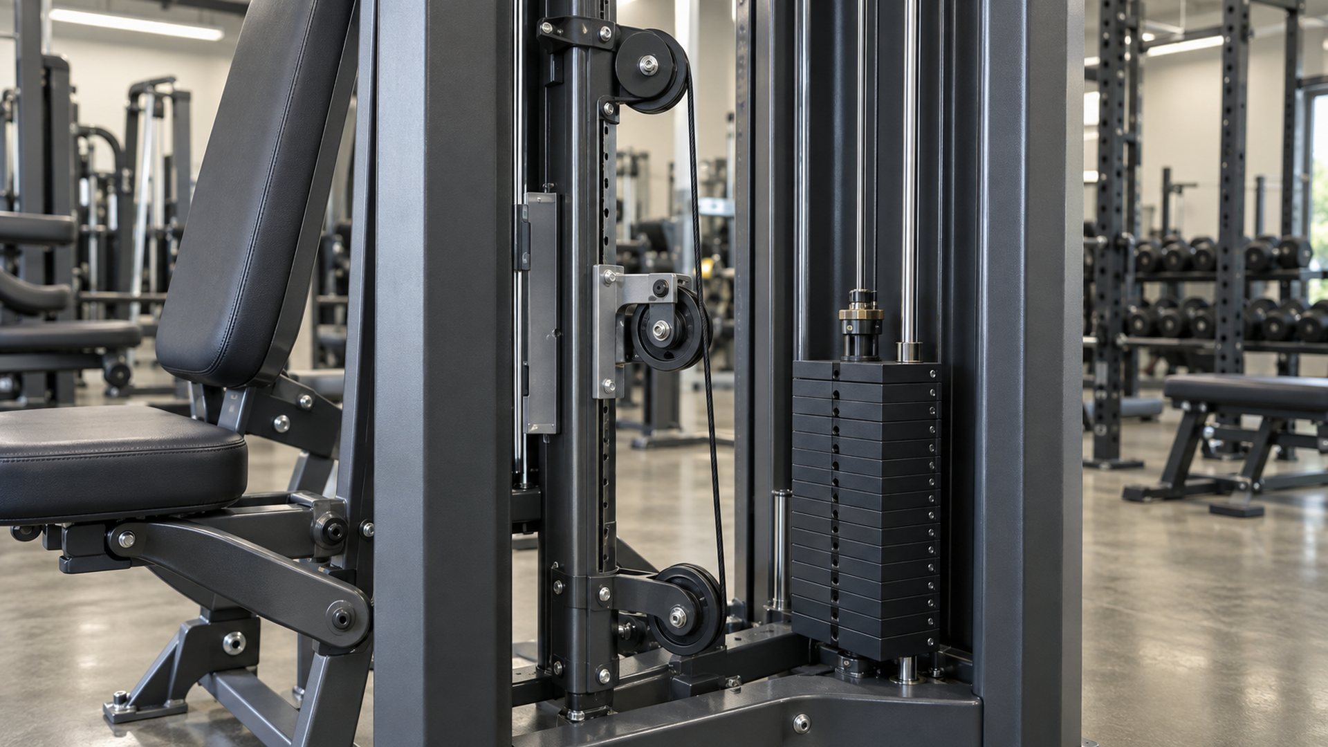
On a selectorized strength machine, several wheels may look similar but perform different functions:
| Pulley position | Main function | System effect | Bearing concern |
|---|---|---|---|
| Fixed direction pulley | Redirects the cable around the frame | Changes cable direction without ideally changing force ratio by itself | Resultant radial load depends strongly on the wrap angle |
| Moving pulley | Travels with a weight carriage or moving arm | Changes handle travel and mechanical advantage | Load must be evaluated with all supporting cable segments |
| Guide pulley | Controls routing and clearance | Keeps the cable away from covers, tubes or other mechanisms | Side alignment and flange contact become important |
| Tensioning pulley | Maintains cable position or preload | Reduces slack within a defined mechanism | Continuous contact, bearing drag and adjustment range matter |
For an ideal single fixed pulley, the input tension and output tension are equal, and the wheel only redirects the force. Real systems are not ideal: bearing drag, cable bending and contact with guides create some difference between the two sides.
A moving pulley is different. When two cable segments support a moving block, each segment contributes to supporting the load. This can reduce the handle force relative to the load, while increasing handle travel relative to stack travel. Compound gym machines can use several fixed and moving pulleys, so the complete routing diagram is needed before anyone labels the system 1:1, 2:1 or another ratio.
How Does Cable Tension Become Bearing Load?
The bearing carries the vector sum of the tensions in the two cable segments, not simply the selected weight printed on the stack.
If the tensions on both sides of an ideal pulley are approximately equal to T, and the cable changes travel direction by an angle θ, the approximate force acting on the pulley is:
R = 2T × sin(θ/2)
In this expression, θ is the change in cable travel direction. The result shows why the same cable tension can create different pulley loads:
- A nearly straight cable path produces a relatively small resultant force on the pulley.
- A 90-degree redirection produces an ideal resultant of about 1.41T.
- A 180-degree reversal produces an ideal resultant close to 2T.
This formula is a useful starting point, not a complete machine rating. The entry and exit tensions can differ because of friction, acceleration, cable stiffness and other components in the route. Dynamic user input, a weight stack reaching the end of travel, or slack being taken up suddenly can also create transient forces above the steady operating condition.
I would calculate each pulley position separately. The calculation should use the real cable directions at that position, then transfer the resultant through the bearing, axle, bracket and frame. A bearing catalogue rating cannot confirm the strength of a thin bracket, an undersized bolt or an unsupported plastic hub.
Why Does the Bearing Reduce Resistance?
Rolling contact generally creates less resistance than a plain plastic bore sliding directly on an axle, especially under repeated load.
In a ball bearing, the balls roll between the inner and outer raceways. The bearing also maintains a defined axis of rotation and separates the pulley from the stationary axle. This helps a cable-operated machine respond more consistently through repeated strokes.
Most small fitness pulleys primarily impose radial load on the bearing. However, the bearing can receive unwanted axial load when:
- the cable approaches the groove at a side angle;
- the two bracket plates are not parallel;
- the pulley is offset from the cable plane;
- the cable continuously rubs a flange;
- the axle shoulder or spacer stack is not square.
Deep-groove ball bearings can accept some combined load, but they are rigid bearings and tolerate only limited misalignment. SKF’s bearing damage and failure analysis guidance shows how excessive misalignment or axial loading changes the raceway contact pattern and can reduce bearing life. For an OEM design, the better response is to correct the cable and bracket geometry rather than ask the bearing to compensate for poor alignment.
For a broader explanation of pulley structures and bearing arrangements, see HUNE’s pulley bearing engineering guide.
Why Does the Weight Stack Number Not Equal the Pulley Load?
The user’s selected resistance, cable tension and load on each pulley are related, but they are not interchangeable values.
The number printed beside the weight stack describes the selected mass or intended user resistance under the machine’s designed ratio. A pulley bearing load still depends on several other variables:
- Mechanical ratio. A moving pulley can divide the supported load among multiple cable segments.
- Pulley wrap angle. The direction change determines how the two cable-tension vectors combine.
- Pulley location. Two wheels in the same machine can experience different cable directions and different resultant loads.
- Moving mass. Handles, arms, carriages and the cable itself must accelerate and decelerate.
- Friction and cable bending. Every pulley and guide adds resistance, so tension may not remain identical throughout a compound route.
- End conditions. A stack landing, a stop being reached, or slack being removed can create a short-duration load different from normal travel.
I would not approve a pulley from a stack label alone. An OEM should provide a cable-path drawing, identify the moving components and define the intended operating and verification conditions.
How Do Groove Geometry and Pulley Diameter Affect the Cable?
The groove has to retain and support the finished cable without pinching its coating or forcing continuous flange contact.
The finished cable diameter includes any polymer coating. That finished diameter, rather than the bare wire-rope diameter alone, should be used to define the groove. A groove that is too narrow can pinch or abrade the coating. A groove that is too wide or shallow can allow unstable tracking. Flanges help retain the cable during normal movement and transients, but they should not be used to correct a permanent side-angle error.
Pulley running diameter also controls cable bending. A smaller diameter packages easily but bends the cable more sharply on every cycle. A larger diameter reduces curvature but consumes more space and can change the machine layout. The acceptable relationship depends on the cable construction, coating, load and supplier guidance; it should be validated with the actual cable rather than copied from an unrelated machine.
HUNE’s article on specifying a bearing pulley for fitness equipment covers groove inputs, wheel materials, sample testing and RFQ details. A U-groove bearing pulley wheel can be a useful starting geometry, but the groove must still match the real cable and duty.
What Makes a Fitness Cable Pulley Feel Smooth and Quiet?
Smooth operation comes from the complete cable path; a high-grade bearing cannot correct runout, side rubbing or a poor bracket stack.
The main contributors are:
- Pulley concentricity and running-diameter variation. Excessive variation can change cable position and tension as the wheel turns.
- Bearing seat geometry. An overly tight moulded seat can compress the outer ring; a loose seat can allow movement or noise.
- Axle and spacer control. The inner ring needs stable support without bracket contact against the rotating wheel.
- Cable-plane alignment. Persistent flange contact creates rubbing, coating wear and additional axial load.
- Groove surface and material. Surface condition, stiffness and damping affect cable contact and sound.
- Bearing closure and lubricant. Seals usually provide better contamination protection but can add drag; shields generally have lower seal contact but less exclusion against fine debris.
- Weight-stack guides and other joints. Noise attributed to a pulley may actually come from guide rods, cable terminations, covers or frame joints.
For the closure trade-off, see sealed vs shielded bearings. I normally make that choice from contamination exposure, acceptable torque, service expectation and complete-machine validation, rather than treating one closure as universally better.
How Should an OEM Validate the Pulley System?
Validate the installed assembly under the real cable route; a loose component spin test is only an incoming check.
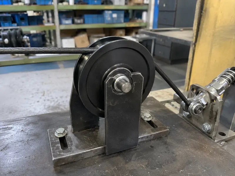 I use a staged approach:
- Confirm the geometry. Check pulley position, cable entry and exit angles, groove fit, clearances and bracket alignment from the drawing and assembled machine.
- Calculate the load path. Determine cable tensions and the resultant at each pulley, including the moving-pulley ratio and relevant dynamic conditions.
- Inspect functional dimensions. Measure running diameter, groove profile, wheel width, bearing location, axle diameter, spacer length and bracket gap.
- Tighten the real joint. Verify that the pulley still rotates freely at the specified fastener condition and does not contact the bracket.
- Observe tracking through full travel. The cable should remain supported in the groove without continuous flange rubbing or interference with nearby parts.
- Run the applicable equipment test plan. Evaluate repeated cycles, maximum intended conditions and foreseeable transitions defined by the OEM.
- Inspect after testing. Look for cable-coating marks, groove wear, bearing looseness, cracked hubs, bracket deformation and changes in noise or torque.
ISO 20957-1:2024 establishes general safety requirements and test methods for indoor stationary training equipment. For selectorized strength equipment, ASTM F2216-17a(2025) establishes design and manufacturing guidelines and is used with related ASTM fitness-equipment standards. The equipment manufacturer must determine which standard and market requirements apply to the complete product. A pulley or bearing by itself does not make a machine compliant.
What Should a Buyer Send to a Pulley Supplier?
A useful request describes the installed cable system and approval method, not only pulley diameter and price.
Send the supplier:
- a pulley drawing or 3D model with controlled functional dimensions;
- the pulley position and a cable-routing diagram;
- finished cable diameter, coating material and cable supplier information;
- pulley outside diameter, running diameter, groove profile and wheel width;
- bearing designation or required bore, outside diameter and width;
- axle, spacer and bracket geometry, including tightening method;
- calculated cable tensions, direction-change angles and resultant loads for each position;
- speed, duty cycle, operating environment and expected service conditions;
- applicable safety standard and the OEM’s validation plan;
- material, colour, appearance and traceability requirements;
- prototype, pilot and production quantities.
Where a standard wheel is not suitable, the supplier may need to coordinate the moulded pulley body, bearing fit, axle support and bracket clearances. HUNE’s OEM development process explains the progression from requirements and drawings to samples and production control.
Discuss a Fitness Equipment Cable Pulley with HUNE
HUNE, Zhejiang Huaneng Micro Bearing Co., Ltd., manufactures bearings, plastic-coated bearing wheels, injection-moulded pulleys and customised roller assemblies for OEM applications. For a fitness equipment project, we can review the pulley wheel, bearing, cable interface, axle and bracket as one working assembly.
Send your cable diameter, routing drawing, pulley dimensions, calculated loads, bracket details, test plan and required quantity through the HUNE contact page. Clear system information helps us assess whether an existing pulley is suitable or a custom wheel and assembly should be developed.
Frequently Asked Questions
Does a fixed pulley reduce the force needed to lift a weight stack?
A single ideal fixed pulley mainly changes the direction of force. It does not create mechanical advantage by itself. A machine’s resistance ratio changes when moving pulleys or other linkages alter how many cable segments support the moving load.
Why can a pulley bearing carry more force than the selected weight suggests?
The bearing reacts to the combined tension vectors on both sides of the pulley. A large direction change can produce a resultant greater than the tension in either individual cable segment. Dynamic motion and friction can also change the actual load.
Do two bearings automatically double a pulley’s load capacity?
No. Two bearings may improve support and moment resistance, but load sharing depends on bearing spacing, fits, axle stiffness, bracket alignment and manufacturing variation. The wheel hub, axle and bracket may become the limiting parts.
Should fitness equipment pulleys use sealed or shielded bearings?
It depends on contamination exposure, allowable rotational drag, lubricant retention and service expectation. The choice should be tested in the assembled pulley because seals, fits and fastener clamping all influence running torque.
What determines whether a gym cable system is 1:1 or 2:1?
The routing and the number of cable segments supporting each moving pulley or carriage determine the ideal motion and force ratio. The complete cable diagram is required; counting the total number of pulleys does not identify the ratio.
Practical Engineering Recommendation
Map the full cable route and calculate every pulley position before selecting the bearing wheel. Begin with the finished cable, direction-change angles, moving-pulley arrangement and expected dynamics. Then confirm groove geometry, bearing fit, axle support and bracket alignment in an installed sample. Approve production only after the complete machine has passed the OEM’s applicable safety and endurance validation.


