

Most automatic elevator doors work through a motorized operator on the elevator car. At the served floor, a coupling links the car doors to the landing doors so they open and close together. Hanger rollers support the panels on horizontal tracks, while lower guides keep them aligned. Door locks and electrical monitoring control normal travel permission; obstruction sensors support reopening during closing.
These functions depend on different components. A bearing helps a wheel rotate, a rail establishes its path, and a door interlock performs a separate safety function. Understanding those differences is useful when specifying rollers for an OEM door mechanism.
This guide covers common horizontally sliding automatic passenger elevator doors. Manual doors, vertical freight doors and specialized entrance systems use different arrangements.
Why Are There Two Sets of Elevator Doors?
The car doors travel with the cabin; the landing doors stay at each floor.
The doors passengers see inside the elevator belong to the car. A second set closes the entrance to the shaft at each landing. When the car serves that floor, both sets form a passage into the cabin.
Each assembly has its own mounting structure and guidance. Their panels move together during passenger access, but they remain mechanically distinct. Landing doors at other floors remain closed and locked during normal service.
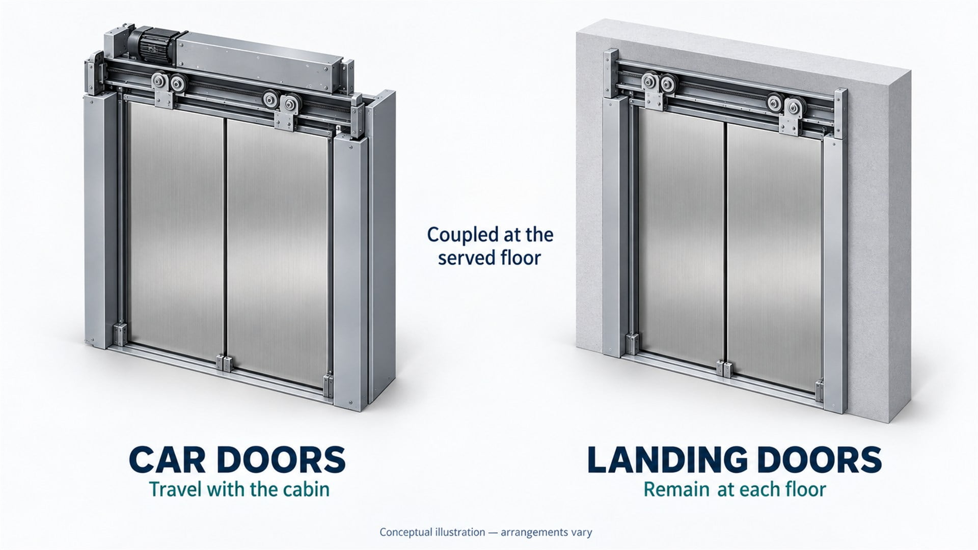 The two door assemblies meet at the served floor. This illustration separates them for clarity; actual coupling and header arrangements vary.
In a common arrangement, the car carries the powered door operator and transfers opening motion to the selected landing doors through a coupler. This avoids needing an identical powered operator at every entrance, although independently driven landing-door designs also exist.
For a buyer, identifying which assembly a component belongs to is the first step. “Elevator door roller” alone does not establish its mounting position, mating surface or operating duty.
How Does the Opening and Closing Sequence Work?
The operator moves the panels, while the controller coordinates access and verifies the required door conditions.
The following sequence describes an ordinary passenger stop. Exact timing and permitted operating modes depend on the elevator design.
1. The Car Reaches the Served Landing
The elevator control system establishes that the car is in the appropriate landing zone and permits the door-opening sequence. This is a coordinated control decision, rather than a wheel or mechanical stop determining when passengers can enter.
2. The Door Coupling Engages
In a common vane-and-roller design, the car-side coupler interacts with landing-door pickup rollers. The mechanism coordinates landing-door unlocking and transfers horizontal movement between the assemblies. One published example shows how vanes engage landing-door rollers for joint movement and disengage for car travel. It illustrates a particular design, not a universal coupling geometry. See the elevator door coupler and latch patent.
3. The Operator Opens the Panels
An electric motor supplies movement through a belt, linkage or another transmission. A center-opening arrangement moves panels away from the middle. A telescopic arrangement moves overlapping panels at coordinated speeds to clear the opening.
Modern closed-loop operators use feedback to control movement. For example, the HD-LM door operator technical manual documents motor encoder feedback, door-position sensing and controlled motion parameters. The drive arrangement and control settings are specific to that operator.
4. The Doors Remain Open for Access
The controller manages the opening period using the applicable operating logic and input signals. Door-open commands and obstruction detection can influence the sequence. The system then initiates closing when the relevant conditions allow it.
5. The Panels Close and Lock Status Is Verified
The operator brings the assemblies toward their closed positions. Landing-door closing devices contribute according to the mechanism design, and the locks return to their secured state. Normal travel requires the specified door-closed and locking conditions to be established.
That description should not be turned into an absolute claim that every elevator has identical behavior in every mode. Special leveling and other controlled functions are governed by the equipment design and applicable requirements.
What Do Elevator Door Rollers and Bearings Do?
Hanger rollers support horizontal door movement; bearings let those rollers turn around their axles.
In a typical top-hung door, the panel hangs from brackets connected to rollers running along a header rail. The wheel tread contacts the rail. Its bearing provides the rotating interface around the axle, while the hanger and fasteners connect the assembly to the panel.
The lower edge is commonly guided by shoes, also called gibs, traveling in a sill groove. Their usual role is to constrain lateral movement rather than carry the panel's main vertical weight. The background and drawings of this elevator door guide assembly patent explain the relationship between upper rollers, lower guides and track retention features.
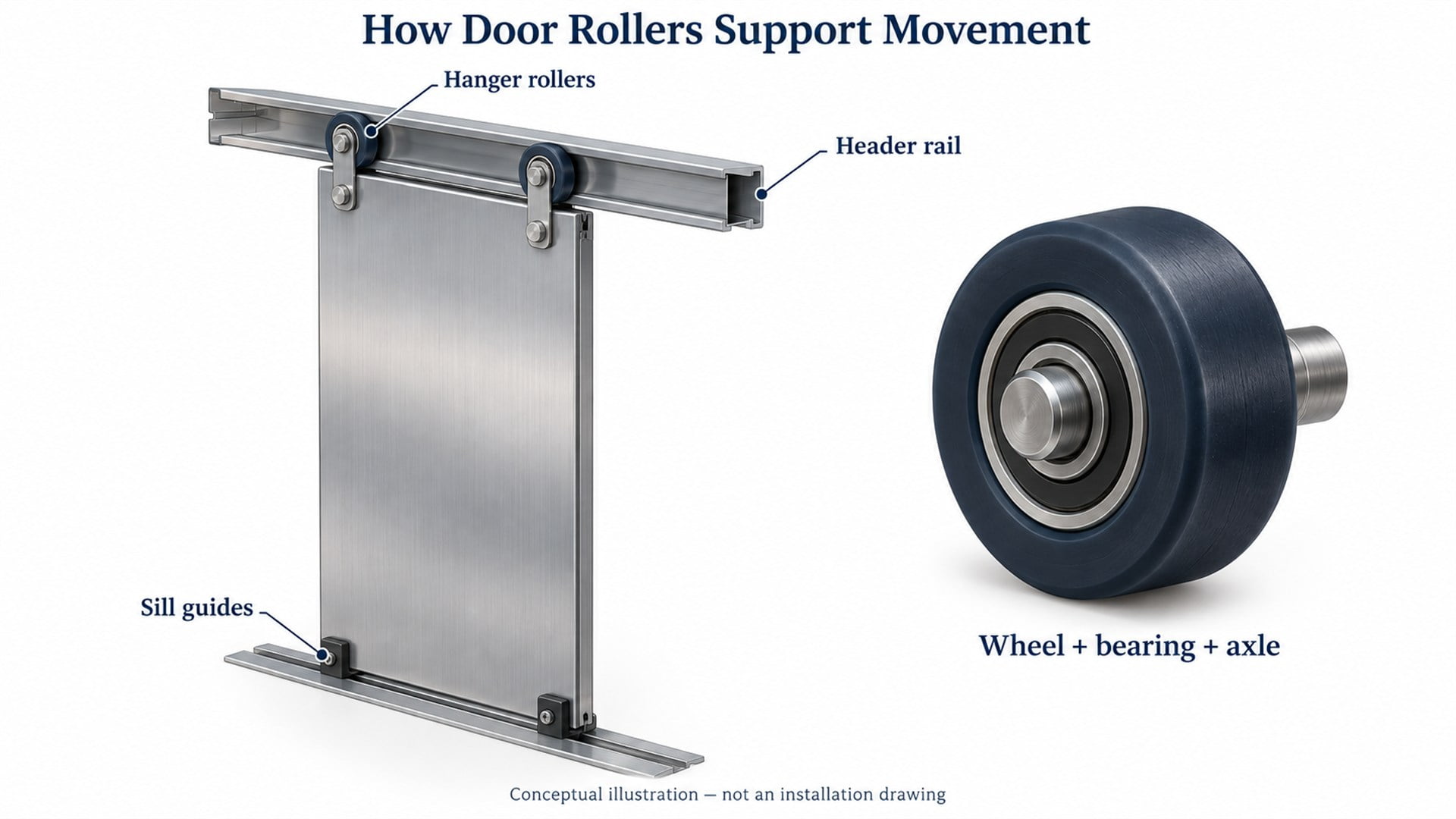 Upper support and lower guidance work together. The simplified illustration is not an installation drawing and omits design-specific retention and operating hardware.
Several parts can be called rollers, but they perform different jobs:
| Component | Primary function | Interface the buyer must identify |
|---|---|---|
| Door hanger roller | Supports the door panel as it travels horizontally | Header rail, hanger and axle |
| Coupling or pickup roller | Transfers contact forces within the door coupling | Vane or cam, pivot and mounting bracket |
| Retention or upthrust roller, where fitted | Helps limit unwanted movement relative to the track | Track underside or designated retaining surface |
| Drive pulley or idler | Transmits or guides belt movement | Belt profile, shaft and transmission layout |
| Car guide roller | Guides the elevator car along its vertical rails | Car guide assembly and vertical guide rail |
A car guide roller belongs to the system guiding the cabin through the shaft. Its duty cannot be inferred from a door hanger wheel of similar appearance.
Our explanation of bearing roller construction and selection provides background on the wheel, bearing and mounting interface. For elevator applications, that component-level understanding must be combined with the door manufacturer's approved assembly requirements.
How Do Door Locks Differ from Obstruction Sensors?
Locks secure the entrance; obstruction sensors help manage closing around passengers.
A landing-door interlock combines a mechanical locking function with electrical verification of the required condition. Car-door monitoring and locking arrangements depend on the system. These functions contribute to the conditions required for normal elevator travel. EMSD's lift inspection and maintenance checklist identifies mechanical locks, electrical contacts, door guiding and passenger protective devices as separate items.
A light curtain detects interruptions across the entrance using multiple light beams. During ordinary closing, an obstruction signal can cause reopening according to the control logic. A contact safety edge responds through physical contact. EMSD's guide to lift safety devices distinguishes light sensors from contact-operated safety edges.
Successful obstacle detection does not demonstrate that a mechanical lock is engaged. Equally, a correctly engaged lock does not establish that the light curtain covers the entrance properly. Each function needs its own verification within the complete door system.
For component procurement, smooth roller movement is one requirement among several. It does not certify the locking mechanism, protective devices or complete entrance assembly.
Which Roller Dimensions and Mating Surfaces Matter Most?
A matching outside diameter is only the beginning of a functional match.
When I review a roller drawing, I first want to see the rail section and mounting arrangement. A wheel can fit on the axle yet contact the rail at an unintended edge, interfere with the bracket or place the panel at the wrong height.
The specification should define the interfaces that control movement:
| Feature | Why it matters in the assembly | Information to provide |
|---|---|---|
| Tread or groove profile | Establishes where the wheel contacts the rail or coupling surface | Wheel section and mating profile, including relevant radii |
| Effective running diameter | Influences supported position and rolling behavior | Defined measurement surface and approved dimensional limits |
| Wheel width and hub offset | Affect bracket clearance and the contact plane | Widths, offsets and assembly datums |
| Bearing bore and axle shoulder | Determine fit and how the inner ring is located | Bearing designation, axle drawing and shoulder geometry |
| Bearing seat in the wheel | Influences retention and the bearing's installed condition | Seat geometry, material and intended assembly process |
| Spacers and clamping faces | Determine the load path through the mounting stack | Section view showing rings, spacers and fasteners |
| Runout and mounting alignment | Affect variation in contact and panel movement | Required runout controls and agreed inspection method |
There is no useful universal tolerance for all these dimensions. Functional limits should come from the approved door design and its tolerance analysis.
HUNE's U-groove bearing wheels illustrate how a shaped polymer running surface and a metal bearing can form one component. The catalog is a starting point for discussing construction; an elevator door application requires a separate suitability review.
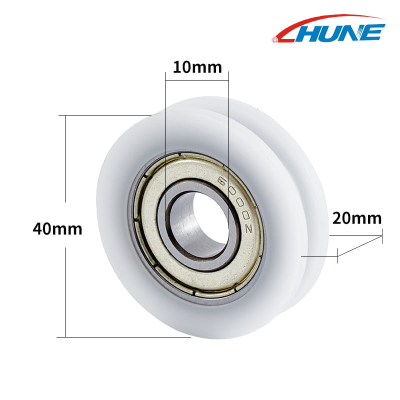 Existing HUNE product photograph. The marked dimensions describe this catalog model; they are not recommended elevator-door dimensions or evidence of elevator approval.
The important question is where the assembled wheel will run and how forces will pass through it. A groove selected for a cord, for example, should not be assumed to match a door rail simply because both have rounded surfaces.
How Should OEM Buyers Specify the Complete Roller Assembly?
Specify the operating conditions and acceptance criteria before comparing unit prices.
I would evaluate a proposed roller using its complete mounting stack and mating surface. A freely spinning sample on a desk provides little evidence about performance under door load, repeated reversals or bracket misalignment.
Define the Material and Operating Environment
Wheel selection involves the actual polymer or elastomer grade, bearing construction, lubrication, temperature, moisture and cleaning exposure. A material name alone does not establish dimensional stability, wear behavior or compliance with project requirements.
The tread also affects contact compliance and noise transmission. A softer surface can change deformation under load; a harder surface can change how vibration passes into the panel. Those effects need evaluation in the intended assembly rather than a blanket claim that one material is always quieter.
Separate Bearing Capacity from Assembly Performance
A bearing rating does not automatically rate the polymer tread, axle, bracket or complete door. Specify the load direction and duty at the roller position, including repeated starts and reversals. The supplier needs that information to assess the component instead of relying only on the total mass of the door.
Likewise, dividing panel weight equally between all visible wheels can be misleading if the geometry or load sharing differs. The door designer should establish the component loads used for selection and validation.
Agree on Production and Validation Requirements
For development quantities and repeat production, the manufacturing route can affect tooling, material choices and inspection planning. Our comparison of machined and injection-moulded POM rollers explains factors to review when selecting that route.
Before sample approval, agree on measurable acceptance criteria for dimensions, assembled running behavior, retention, wear and noise where relevant. Define the test fixture, loading, duty and environment so results correspond to the intended application. Production approval should also address material traceability and control of subsequent changes.
For elevator equipment, component acceptance must fit the elevator or door manufacturer's qualification process and the applicable project requirements. A catalog description alone cannot establish suitability for a safety-related assembly.
Frequently Asked Questions
Does Every Elevator Landing Door Have Its Own Motor?
No. In a common passenger elevator arrangement, the powered operator travels with the car and moves the selected landing doors through a mechanical coupling. Each landing retains its own entrance assembly and locking hardware. Other architectures use independently powered landing doors, so the mechanism should be identified before specifying components or assuming a particular transmission layout.
Do Elevator Door Rollers Carry the Weight of the Elevator?
Door hanger rollers carry loads associated with their door panels, not the entire elevator car. The cabin's suspension, support and vertical guidance involve other equipment. Even within the door mechanism, hanger rollers and coupling rollers experience different duties. A purchase specification should name the component position and load case rather than use “elevator roller” as a complete description.
Why Can Elevator Doors Reopen Before They Fully Close?
During ordinary closing, an interrupted light curtain or an activated safety edge can request reopening. Door-open commands and other control conditions may also affect the sequence. Reopening is therefore not, by itself, evidence of a defective roller. Understanding the cause requires the control state and mechanical condition to be evaluated together by the personnel responsible for the equipment.
Can a Standard Sliding Roller with Bearing Be Used in an Elevator Door?
Possibly, but only after the specific component and application have been qualified. Matching diameter and bore does not establish the correct running profile, load capacity, retention or durability. The wheel, bearing, axle and bracket must meet the approved assembly requirements. A standard industrial roller should not be presented as an interchangeable elevator component without that documented review.
Discuss an OEM Roller Requirement with HUNE
HUNE manufactures sliding rollers, bearing wheels and related hardware, with options for customized wheel profiles and mounting arrangements. Our sliding rollers with bearings provide examples for an initial component discussion.
For an elevator-related inquiry, please send:
- The component's exact role: hanger, coupling, retention or another specified position.
- An approved drawing or sample, together with the rail, vane or other mating geometry.
- Bearing, axle, spacer and bracket details, including functional dimensions and datums.
- The operating load, movement duty, environment and material requirements.
- Required validation, traceability and approval documents, plus sample and production quantities.
Use our contact form to send your drawings and OEM roller requirements. Start with the complete interface and the door manufacturer's acceptance criteria; then determine whether an existing design can be qualified or a custom component needs to be developed.


