

The main components of an automatic elevator door system are the car and landing door panels, door operator, drive transmission, hangers, bearing rollers, header rails, sill guides, car-to-landing coupling, mechanical locks with electrical interlocks, position feedback and passenger-detection devices. Each part has a different job: the operator creates motion, rollers carry and guide the panels, the coupling synchronizes the two entrances, and the safety circuit verifies the required door condition before normal travel.
For OEM sourcing, these parts should be specified as one interacting system. A roller that matches the outside diameter may still be wrong if its tread, bearing, axle, bracket or rail contact differs from the approved geometry.
This article describes common horizontally sliding automatic passenger elevator doors. Freight, vertical-opening, manual and independently powered landing-door systems can use different components.
The Component Map at a Glance
An elevator entrance combines structural, motion, coupling and safety components.
The car carries one set of doors. Every served floor has a separate landing entrance. The car-side operator usually powers the opening cycle and transfers movement to the selected landing doors through a coupling mechanism.
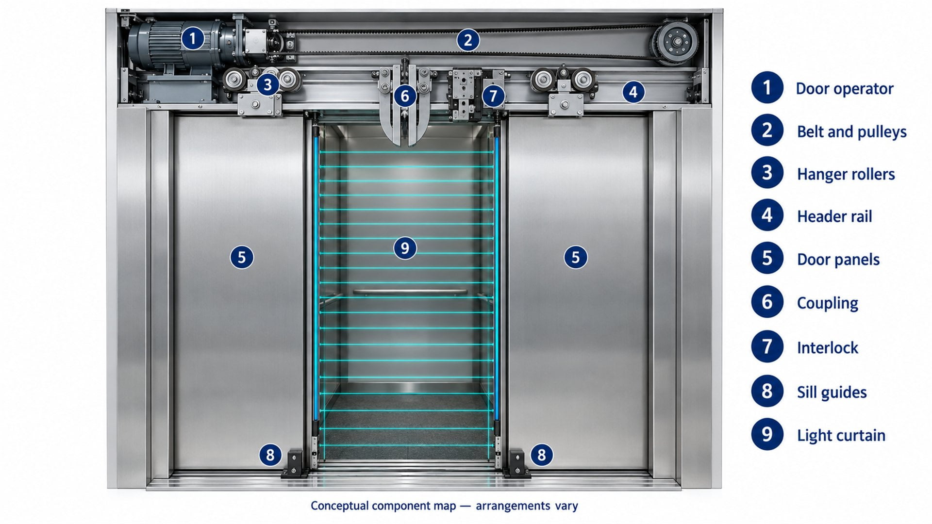 Conceptual component map. It shows functional groups rather than a universal installation; panel count, transmission and coupling architecture vary by manufacturer.
| Component group | Typical parts | Primary function |
|---|---|---|
| Entrance structure | Car doors, landing doors, frames and headers | Closes the car and shaft entrances |
| Motion source | Motor, controller and position feedback | Creates and regulates opening and closing motion |
| Transmission | Belt, pulleys, arms, cables or linkages | Transfers motor movement to one or more panels |
| Upper support | Hangers, bearing rollers, rails and retainers | Carries each panel and establishes its horizontal path |
| Lower guidance | Sill, groove and guide shoes or gibs | Restrains movement transverse to the intended path |
| Door coupling | Vanes, pickup rollers and connecting linkage | Couples car and landing doors at the served floor |
| Locking and verification | Mechanical locks, electrical contacts and monitoring | Establishes and reports the required door condition |
| Passenger protection | Light curtain, safety edge and related inputs | Detects an obstruction during the closing sequence |
The groups interact, but their functions should not be confused. For example, a light curtain can request reopening; it does not mechanically lock the landing entrance. A door roller supports movement; it does not prove that the door-closed circuit is valid.
What Are the Car Doors and Landing Doors?
The car doors move with the cabin, while a separate landing-door assembly remains at each floor.
Car door panels close the passenger entrance to the elevator cabin. Their header, hangers, rollers, operator and coupling equipment travel with the car. Landing doors close the corresponding opening in the shaft enclosure and remain at their floors.
At a normal stop, the two sets align and open together. When the car leaves, the landing entrance must remain closed and secured. This is why a complete bill of materials must identify whether a part belongs to the car door, landing door or coupling between them.
Door configuration also matters. A center-opening entrance has panels moving away from the center in opposite directions. A side-opening entrance moves panels toward one side. Telescopic doors require synchronization between fast and slow panels, adding pulleys, cables, tracks or linkages according to the design.
The panel itself is therefore only one member of an assembly. Its mass, width, stiffness, hanger attachment points and lower-guide locations affect the demands placed on the moving hardware.
What Does the Door Operator Include?
The operator converts an electrical command into a controlled door-motion profile.
A typical car-top door operator includes an electric motor, power electronics, a controller and mechanical transmission. The motor may drive a toothed belt, V-belt, chain, arm or another linkage. Pulleys and idlers establish the motion path and transfer force to the hanger or drive arm.
Position information comes from an encoder, magnetic sensor, limit device or another feedback arrangement. The controller uses this information to manage acceleration, running speed, deceleration and the final closed position. These controls help the operator move doors smoothly under changing friction and air pressure, but the specific profile and settings belong to the approved system.
The HD-LM door operator technical manual provides one real example containing a motor, encoder, drive sheaves, belts, arms, position sensors and a control board. It is useful evidence of how a commercial operator is organized; it is not a universal parts list or a setup guide for other equipment.
For procurement, motor power by itself is not enough. The buyer should define door arrangement, panel mass, opening width, required duty, drive geometry and control interface. A mechanically unsuitable pulley or bearing can cause problems even when the motor and electronics meet their separate specifications.
How Do the Rollers, Rails and Sill Guides Work Together?
Upper components support the panel; lower components keep its bottom edge aligned.
In a common top-hung assembly, each panel attaches to a hanger plate. Bearing rollers on that hanger run along a horizontal rail in the header. The wheel tread creates the rolling contact, the bearing permits rotation around the axle, and the hanger transfers the panel load into the roller assembly.
A retention or upthrust roller may run near another surface of the track to limit unwanted movement. It should not be grouped with the main load-carrying roller simply because both are round. Contact direction and load case differ.
At the lower edge, guide shoes or gibs travel in a sill groove. They primarily constrain lateral movement and help the panel remain aligned. A published elevator door system description identifies the panels, header, track, rollers, hangers, sill and lower door shoes as coordinated components. Another elevator door guide reference explains upper roller support and lower gib guidance in more detail.
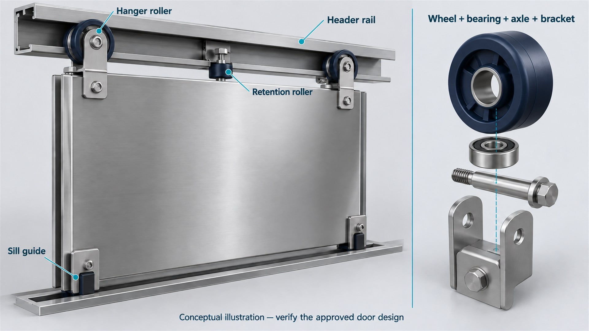 The wheel, bearing, axle, bracket and mating rail form one load path. The illustration is explanatory and should not be used as an installation drawing.
I treat the interfaces as a chain:
Door panel → hanger bracket → axle → bearing → wheel body → tread contact → header rail → supporting frame
Changing any link can affect panel position or rolling behavior. The HUNE guide to bearing roller construction explains why the outside wheel and its internal bearing must be considered together.
Which Roller Dimensions Are Functionally Important?
Running profile and mounting geometry matter more than a catalog diameter alone.
An OEM roller drawing should define the surfaces that control installation, contact and rotation. I would ask for the mating rail section before approving the wheel profile.
| Functional feature | What it controls | Information required from the buyer |
|---|---|---|
| Tread or groove profile | Contact location and pressure distribution on the rail | Rail section, intended contact surfaces and relevant radii or angles |
| Effective running diameter | Supported door position and rolling geometry | Diameter measured at a defined contact datum |
| Wheel and hub width | Clearance inside the hanger and alignment with the rail | Bracket section, spacers and axial-clearance requirement |
| Bearing bore and axle seat | Fit, rotation and transfer of force | Bearing designation, shaft diameter, shoulder and retention method |
| Bearing seat in the wheel | Support and retention of the bearing outer ring | Seat geometry, wheel material and assembly process |
| Axial location | Whether the wheel remains on its intended contact path | Shoulder, washer, spacer and clamping-face dimensions |
| Radial and axial runout | Variation of the running surface during rotation | Datum scheme and agreed inspection method |
There is no responsible universal tolerance for every elevator door roller. Limits should come from the door designer's stack-up, rail clearance and approved validation plan.
HUNE manufactures polymer-covered bearing wheels in several constructions. The following media-library image shows two examples of an outer running surface combined with a metal bearing.
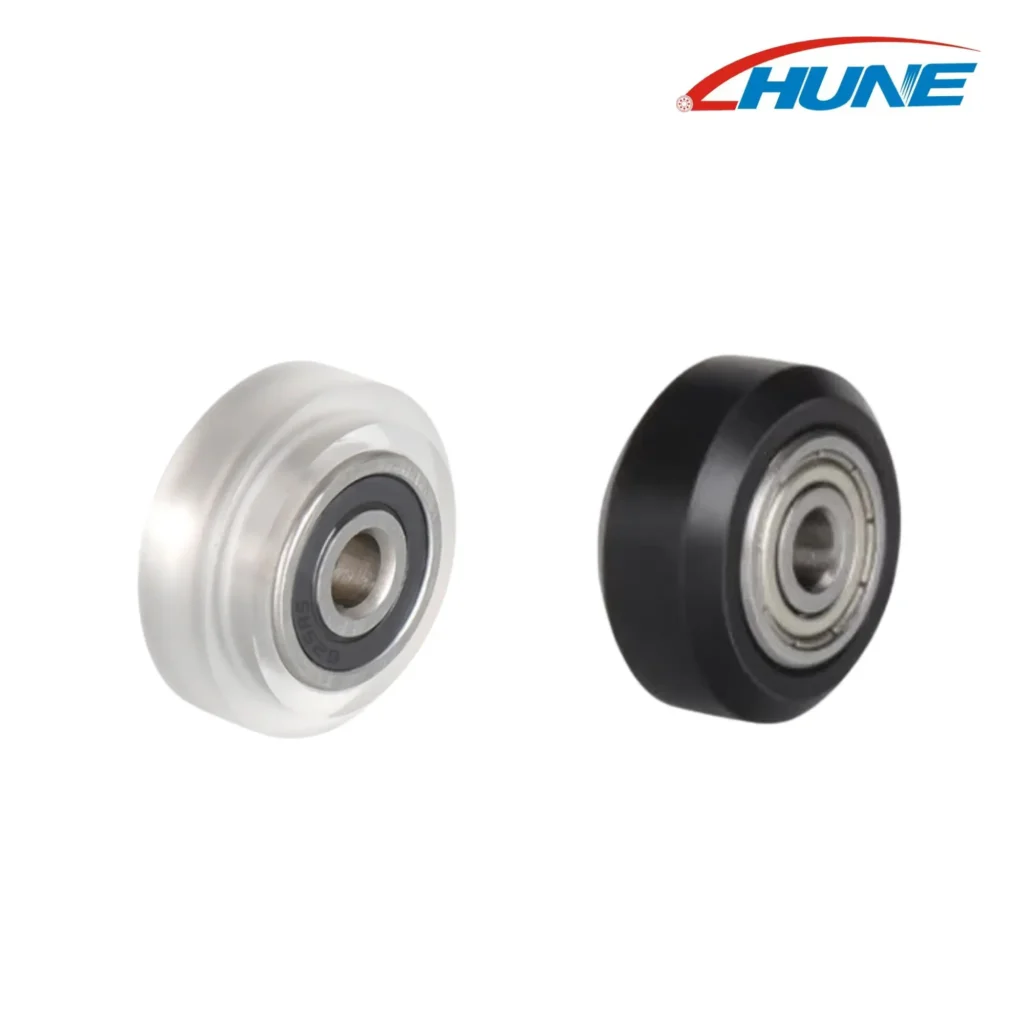 Existing HUNE media-library image. These are component examples, not evidence that a catalog roller is approved for an elevator door system.
Our sliding rollers with bearings offer a useful starting point for discussing wheel construction. Where a rounded contact profile is required, U-groove bearing wheels illustrate one possible geometry. The actual elevator rail must determine whether any such profile is relevant.
What Does the Car-to-Landing Door Coupling Do?
The coupling transfers car-door movement to the landing doors only at the served entrance.
A common coupling uses vertical vanes or cams on the car door and pickup rollers on the landing-door mechanism. When the car is correctly positioned, relative movement brings those parts into controlled contact. The coupling then coordinates landing-door unlocking and moves both assemblies during the access cycle.
The coupling rollers are not ordinary door-support wheels. They experience contact from vanes or cams, may pivot with the lock mechanism and have a different mounting arrangement. Their outside profile, axle support, spacing and relationship to the vanes are all functional.
The drawings and description in this elevator car and landing-door coupling patent show one vane-and-roller solution. Other designs achieve the same broad function differently, so a supplier should reproduce the approved interface rather than generalize from a single mechanism.
For sourcing, the coupling drawing should show roller center distance, vane clearance, pivot points, angular movement, contact faces and the locked and unlocked states. A front-view photograph rarely contains enough information.
What Are the Locks and Electrical Interlocks?
Mechanical locking and electrical verification are related, but they are distinct functions.
Landing doors use a mechanical locking device to secure the entrance. An associated electrical contact reports the required lock condition to the control system. Car doors also have door-closed and locking or monitoring provisions according to the design and applicable requirements.
The safety circuit uses these signals when determining whether normal travel is permitted. A roller cannot substitute for the lock, and low door-operating resistance does not prove that the locking device is correctly engaged.
The mechanical relationship matters here as much as the electrical one. Lock hooks, rollers, cams, springs, pivots, stops and contact actuators must reach their intended positions despite manufacturing variation and wear. The responsible elevator or entrance manufacturer establishes the required geometry, monitoring logic and acceptance procedure.
Which Components Detect Passengers and Door Position?
Passenger detection manages the closing sequence; position feedback manages door motion.
A light curtain places multiple infrared beams across the entrance. When a beam is interrupted during ordinary closing, the signal can request reopening through the controller. A contact safety edge responds when its moving edge is physically actuated. The EMSD guide to common lift safety devices distinguishes light sensors from contact safety edges.
Operator position feedback has another role. An encoder or sensor reports motor or door position so the controller can regulate movement and recognize endpoints. Door-closed and lock contacts provide yet another class of information. These signals may enter the same overall controller, but they do not prove the same condition.
For an OEM bill of materials, name each sensor's target, output, mounting datum, cable interface and environmental requirements. “Door sensor” is too broad for reliable purchasing.
How Should an OEM Buyer Source Elevator Door Components?
Start with the approved assembly and its interfaces, then decide which components can be standardized.
My first step would be to divide the system into safety-critical functional groups and production parts. Door panels, hangers, tracks, coupling hardware and locks must remain coordinated as the drawing changes. A cheaper wheel that moves the panel vertically by a small amount can also change coupling or lock alignment.
Send the component supplier the following information:
- Component name and exact position: car hanger roller, landing hanger roller, coupling pickup roller, retention roller, pulley or another defined part.
- Complete drawing or sample, including the rail, vane, belt or other mating geometry.
- Load direction, operating duty, speed range, reversals, environment and expected service conditions.
- Wheel material grade, bearing construction, lubrication and permitted substances.
- Axle, spacer, washer, fastener and bracket stack with functional datums.
- Required inspection method, validation plan, traceability and change-control process.
- Prototype, first-order and estimated annual quantities.
For grooved parts, the HUNE U-groove roller selection guide explains how track geometry, mounting and load direction affect the decision. If a polymer wheel needs custom production, our comparison of POM roller machining and injection moulding can help plan the prototype-to-production route.
Elevator-related components still require the elevator or door manufacturer's qualification under the applicable project requirements. Product similarity and supplier capability do not establish approval for a safety-related position.
Frequently Asked Questions
Is the Elevator Door Operator the Same as the Elevator Motor?
No. The door operator is the mechanism that opens and closes the entrance panels. It has its own motor, transmission and controls, usually mounted with the car-door equipment. The elevator's main drive moves the car vertically in the shaft. These systems exchange control information, but they perform different mechanical functions and use different components.
What Is the Difference Between a Hanger Roller and a Coupling Roller?
A hanger roller runs on a header rail and supports a door panel through its hanger. A coupling roller contacts a vane, cam or related part to transfer motion or operate a coupling mechanism. Because their contact direction, mounting and load cases differ, one should not be specified from the drawing or rating of the other.
Do the Sill Guides Carry the Door Panel's Weight?
In a common top-hung system, the hanger rollers carry the primary vertical door load. Sill guides constrain the panel's lower edge and resist unwanted transverse movement. Designs vary, and lower components can also contribute to retention. The approved section drawing should therefore define the load path instead of assuming that every part in the sill has the same job.
Can a Standard Bearing Roller Be Used in an Elevator Door?
Only after the specific roller and application have been reviewed and qualified. Matching bore and outside diameter does not establish rail contact, load capacity, retention, durability or system approval. The wheel, bearing, axle, bracket and rail must work together, and the elevator or entrance manufacturer must confirm compliance with its design and validation requirements.
Send Your Elevator Door Roller Requirement to HUNE
HUNE manufactures sliding rollers, polymer-covered bearing wheels and related custom hardware for OEM applications. We can review an existing component, drawing or sample and discuss the wheel profile, bearing, axle, material and production method as one assembly.
Use the HUNE contact form to send your elevator door roller inquiry. Tell us the component's exact function and include its mating geometry and approval requirements. The practical engineering decision is to qualify the complete interface first, then choose an existing roller or develop a custom part around the verified door-system design.


