

Large-format printers transport roll media by unwinding a supply roll, advancing the continuous material through a controlled feed system, supporting it beneath the printheads and collecting the output. Drive rollers provide traction, idlers guide the path, and tension control manages pull between sections. Where fitted, a take-up reel winds the printed material while coordinating with the printer's feed cycle. The exact arrangement depends on the printer and media.
The continuous strip of paper, film, vinyl or textile is often called a web. Unlike separate sheets, it connects upstream and downstream mechanisms throughout the job. A change at the supply roll or take-up can therefore affect conditions near the print zone.
I would start a roller review by identifying which component controls movement, which supports the web and which only guides a mechanical assembly. Those roles require different surfaces, bearings and mounting arrangements.
What Path Does Roll Media Follow Through a Large-Format Printer?
A typical path runs from supply roll to feed mechanism, print zone and output collection, with guides and tension devices where the design requires them.
The transport sequence usually involves these functions:
- Unwinding: A spindle or holder supports the supply roll and allows material to leave it under controlled conditions.
- Guiding: Idlers and other path components direct the web towards the feed section.
- Advancing: A driven roller and opposing pressure rollers, or another designed transport mechanism, move the material through the printing area.
- Supporting the print surface: A platen, sometimes assisted by vacuum, supports the web beneath the printheads.
- Preparing and collecting the output: Where required, drying or curing occurs before the printed web is wound onto a take-up core or collected by another method.
This is a functional sequence, not a universal machine layout. Some printers integrate several functions into a compact path. Others use more distinct transport zones. Ink technology also changes the position and type of drying or curing equipment.
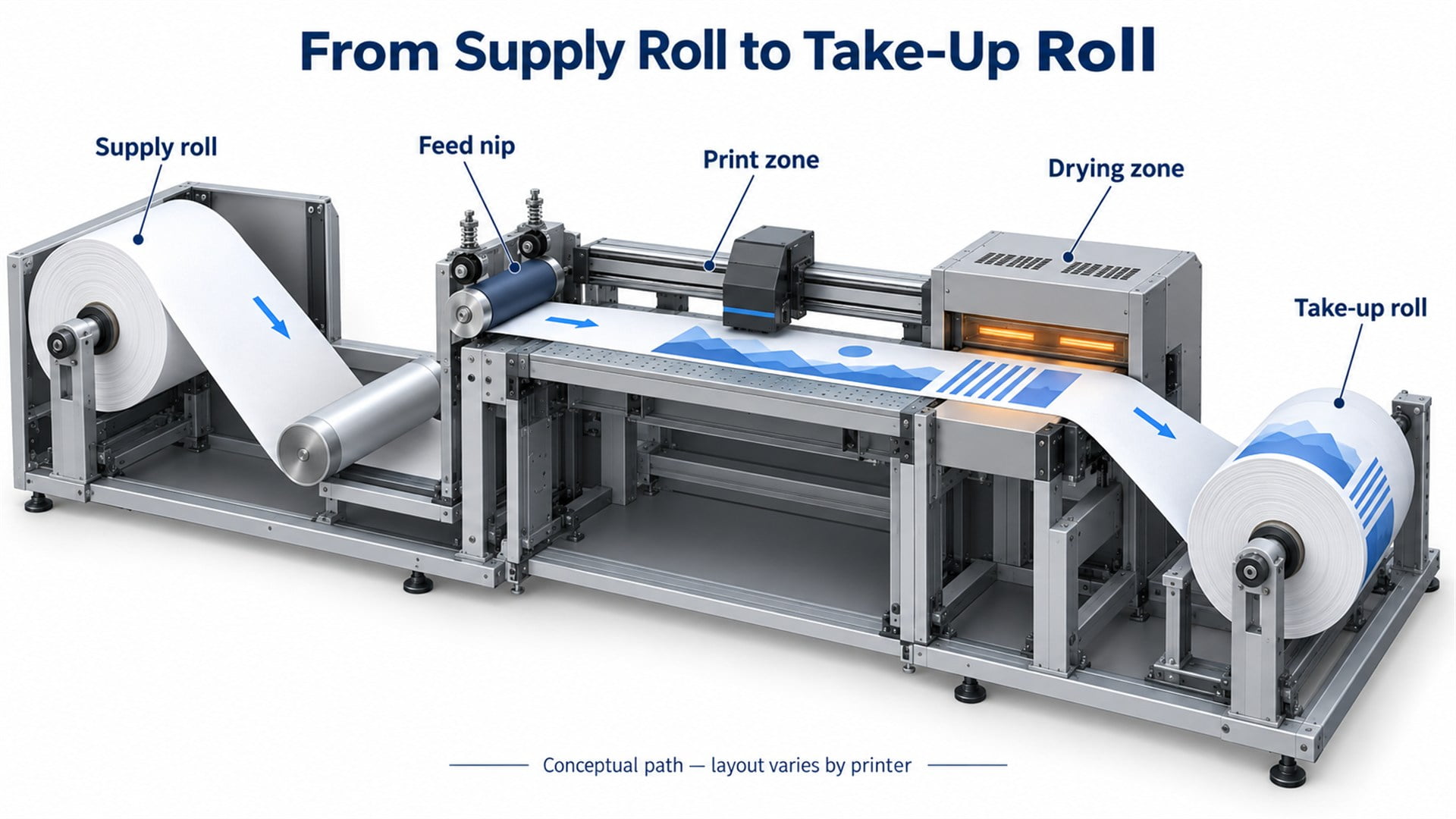
Figure 1. A simplified roll-to-roll transport path. Roller positions, tension devices and drying arrangements vary by printer.
A roll-fed printer normally does not need to separate one sheet from a stack. For that different mechanism, our explanation of how a printer paper feed system works covers pickup and sheet separation.
How Do Feed Rollers Control Media Advance?
The feed mechanism must turn commanded motion into repeatable movement of the actual web.
In a roller-driven system, the motor turns a drive roller. Opposing pinch or pressure rollers hold the media against it, creating the contact needed to transmit force. This contact region is the nip.
The roller surface and nip force must suit the media. Insufficient traction can allow relative movement between the roller and web. Excessive pressure can mark or deform a sensitive surface. A film, a coated paper and a textile do not necessarily require the same contact conditions.
On many scanning printers, media advance is coordinated with successive printhead passes. Other architectures use continuous motion. In either case, motor rotation alone does not prove that the material moved exactly as intended: slip, stretch and the effective roller diameter can affect the result.
Some printers therefore measure media movement directly. HP's explanation of its Optical Media Advance Sensor describes observing the back surface of the substrate to assess movement. It also identifies media for which that sensing method is unsuitable and describes drive-roller encoder feedback as an alternative on the system discussed. This is a model-specific example, not a feature shared by every large-format printer.
For an OEM, the implication is practical: define the required advance performance at the web, then assess the drive, sensing method and roller contact together.
Why Must the System Control Tension as Roll Diameter Changes?
Roll diameter changes the relationship between shaft speed, torque and the pull applied to the web.
At a given web speed, a larger roll turns more slowly than a smaller roll. During a job, the supply roll becomes smaller while the take-up roll becomes larger. A fixed speed relationship between the two spindles would therefore not maintain matching surface speeds throughout the job.
Torque also depends on radius. In a simplified steady-state model, the torque associated with web tension is:
Torque = web tension force × roll radius.
Here, tension force means the total longitudinal pull across the web, not tension per unit width. Acceleration, bearing losses and other mechanical effects add to the real drive requirement. The equation explains the relationship; it is not a motor-sizing calculation by itself.
Depending on the design, an unwind may use controlled braking or a powered drive. A take-up may use torque control, a dancer mechanism or a sensor-controlled loop. A moving dancer can store a limited amount of web and provide a signal for adjusting a drive. A simple weighted tension bar need not provide that same feedback function.
The goal is an appropriate tension condition in each span. Pulling harder everywhere can stretch compliant media or disturb transport, while insufficient control can allow slack. Different zones may intentionally operate at different tension levels.
How Does the Printer Keep the Web Flat and Tracking Straight?
Flatness, lateral tracking and forward advance are related but separate requirements.
A web can move the correct distance and still travel at an angle. It can also remain centred while lifting away from the platen. Each condition points to a different part of the system.
Roller alignment, support rigidity and consistent contact across the width influence the path. The relationship between the supply core, feed rollers and downstream guides matters more than the appearance of one wheel in isolation. A full-width roller also needs sufficient stiffness for its support span and operating loads.
Where vacuum is used, suction holds the material against the platen. It must be balanced with the media's ability to advance. The Epson SC-S9100 Series User's Guide treats feeding tension, paper suction and pressure-roller load as separate controls. Its descriptions connect these settings with waviness, feeding behaviour and surface marking. That separation is useful engineering evidence that one adjustment cannot stand in for every transport requirement.
Temperature and media construction add further variables. A coated film may respond differently from a textile or paper-backed adhesive material. Define the actual media and operating condition before assuming that a roller suitable for one application will behave the same way in another.
What Does the Take-Up Reel Do?
The take-up reel collects printed media while maintaining an output condition compatible with the feed system.
It supports longer runs by winding the output onto a core. Its action must accommodate changes in roll diameter, printer pauses and the behaviour of the printed media.
In systems using a controlled loop, the output can accumulate briefly before the reel winds it. A tension bar or dancer may help manage this section, depending on the machine. For example, the Epson guide cited above identifies a tension bar that prevents slack during winding and an automatic take-up unit that collects printed media.
The take-up should not be treated as an independent winch that determines print advance by pulling harder. Excessive downstream pull can interfere with the feed section; an unsuitable winding condition can also produce a poorly formed output roll.
Winding must additionally respect the printed surface. Contact location, winding direction and the required drying or curing condition belong in the media-handling specification. They cannot be inferred from bearing size.
What Do Bearings and Idler Rollers Contribute?
Bearings support rotation; the roller surface contacts the web, and the axle and frame establish the geometry.
A free-turning idler changes or supports the web path without being the main driven feed element. The moving web must supply the torque needed to rotate it. Bearing resistance and roller inertia therefore matter, particularly during starts or with media that can tolerate only limited pull.
One arrangement uses a stationary axle with bearings inside the roller's end supports. The roller shell turns while the axle remains fixed. Another uses a roller and shaft that rotate together in frame-mounted bearings. These constructions require different bearing fits and retaining details.
MIT's FUNdaMENTALS chapter on bearings emphasises relative motion, force transmission and mechanical constraints. Applied here, that means reviewing the entire support path: web contact, roller body, bearings, shaft or axle, brackets and frame.
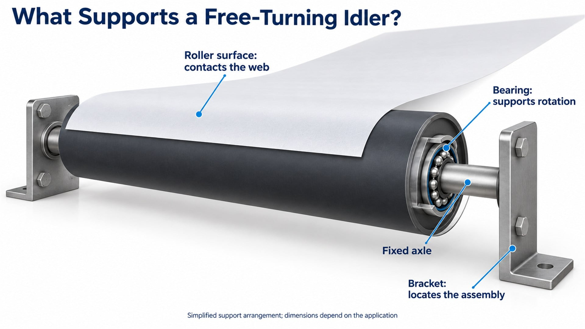
Figure 2. One possible idler construction uses bearings between a rotating roller shell and a fixed axle. This is a conceptual assembly, not a product specification.
A smooth bearing cannot correct an eccentric running surface or a misaligned bracket. Likewise, a properly finished roller can bind if the assembled clamping arrangement loads the wrong surfaces. I would assess running resistance after assembly, alongside runout and clearance, rather than approving the bearing solely by spinning it loose on a bench.
Where Can HUNE Bearing Rollers Fit into This Equipment?
Small bearing wheels can be considered for compatible guide or support mechanisms; full-width media rollers require their own design assessment.
HUNE's flat roller wheels with integrated bearings show how a polymer wheel and bearing can form a compact rolling component. For a printer equipment project, that architecture may be relevant where a small wheel runs against a mating guide or supports a moving mechanical part.
The first check is the contact interface. A wheel running on a rail needs a profile and clearance suited to that rail. A wheel touching a narrow region of media needs separate assessment of contact pressure, marking and the effect on tracking. A full-width idler needs attention to its span, stiffness, surface and end supports.

Figure 3. An existing HUNE flat bearing roller product image. The annotated dimensions identify the illustrated component; they are not recommended dimensions for every printer mechanism.
A hard polymer wheel is therefore not an automatic replacement for a compliant feed roller or a long web-contact roller. Use the product architecture as a starting point and confirm the equipment's functional requirements before selecting a size or material.
What Should OEM Buyers Specify for a Custom Roller?
Define the contact task and mounting geometry before asking suppliers to quote a diameter and bearing.
| Requirement | What to provide | Why it changes the selection |
|---|---|---|
| Component role | Driven feed roller, passive idler, guide wheel or mechanical support wheel | Determines the required traction, resistance and support arrangement |
| Mating interface | Web contact position or rail profile, contact width and entry/exit directions | Establishes the functional running surface and load path |
| Rotation and mounting | Fixed axle or rotating shaft, bearing seats, retention, spacers and bracket drawing | Controls fit, side clearance and assembled rotation |
| Running geometry | Diameter/profile, runout datum, support span and inspection method | Connects the drawing to contact consistency and alignment |
| Duty and environment | Load directions, speed, acceleration, media types, temperature and contaminants | Influences material, bearing and surface requirements |
| Production scope | Exact material grade, prototype quantity, annual demand and supplied assembly content | Makes manufacturing routes and quotations comparable |
For direct web contact, also identify the printable side, allowable marking and any restrictions on lubricant migration. For a guide wheel, send the mating rail section and expected radial or axial loading. If a load or tolerance remains unknown, list it as an open requirement for the equipment designer to resolve.
Manufacturing route should follow design maturity and demand. A machined polymer sample may answer fit questions quickly, while moulded production requires confirmation of the actual material and process result. Our comparison of POM roller machining and injection moulding explains those production choices in more detail.
Approve samples against defined questions: first geometry and mounting, then the intended material and bearing arrangement, then operation in representative equipment. A pilot lot should demonstrate that normal production reproduces the agreed characteristics. For direct media contact, include representative widths and media constructions rather than treating one successful short run as complete validation.
Frequently Asked Questions
What is the difference between roll media and sheet media?
Roll media is a continuous length wound around a core. Sheet media arrives as separate pieces. A roll transport system manages changing roll diameter, continuous web tension and output collection. A sheet-fed system usually adds pickup and separation functions. Both need controlled advance through the print zone, but their upstream and downstream mechanisms serve different purposes.
Does every large-format printer need a take-up reel?
No. The output arrangement depends on the printer, media and job. Some systems collect output in a basket or cut it into sheets, while roll-to-roll production uses a take-up to wind longer continuous output. A take-up is part of a defined transport configuration; its presence alone does not establish better advance accuracy or compatibility with every material.
Can the same roller handle vinyl, paper and textile?
Possibly, if its contact and operating range have been validated for each. These materials can differ in stiffness, surface friction, stretch, backing construction and sensitivity to pressure. The shared roller may also require different machine settings for different media. A common nominal thickness or width is not enough to establish that one roller surface and support arrangement will work across all three.
Does a low-friction bearing mean the roller should have a slippery surface?
No. Low resistance in the bearing concerns rotation within the assembly. Surface friction concerns contact between the roller and the web or guide. A driven feed roller needs suitable traction to move material, while an idler needs to turn readily under its operating conditions. Specify these two interfaces separately rather than using “low friction” as a complete roller requirement.
Discuss a Printer Equipment Roller Project with HUNE
HUNE manufactures custom sliding rollers, plastic bearing wheels and hardware components for OEM applications. Its sliding rollers with bearing range provides structures to compare when a printer mechanism needs a compact rolling guide or support component.
For roll-media equipment, first identify the roller's place in the transport system and the surface it actually contacts. Then review the material, bearing arrangement, mating geometry and required validation together.
To assess a suitable component, send HUNE your printer equipment roller enquiry with the wheel and mating-part drawings, contact function, load direction, operating speed, critical dimensions, media or rail details and expected quantity. Use that information to agree on a sample specification and an installed evaluation before committing to production.


