

Printers keep paper aligned by combining edge guides, controlled roller contact, a stable paper path and, where fitted, registration mechanisms and sensors. Guides establish the starting position; feed rollers move the sheet; registration corrects its position or angle and coordinates arrival at the printing stage. Bearings support the rotating parts, but accurate alignment depends on the complete mechanism, the paper and the control system working together.
A sheet can be straight but shifted sideways, or correctly positioned but arriving too early. These are different errors. I would first identify which one the equipment must control before changing a roller, bearing or guide.
This article focuses on sheet-fed printer mechanisms. Designs vary: a compact inkjet printer and a production electrophotographic printer do not necessarily use the same registration method.
What Does Paper Alignment Actually Mean?
Alignment involves sheet angle, lateral position and position along the feed direction.
Skew means the sheet is rotated relative to the intended path. One leading corner reaches a transverse reference before the other.
Lateral position describes where the sheet sits across the path. A sheet may travel straight while remaining too far left or right.
Process-direction registration concerns the sheet's position or arrival timing along its direction of travel. The printing system needs the image and paper to meet at the intended location.
These distinctions matter when defining acceptance criteria. A single instruction such as “keep the paper straight” does not specify allowable skew, side offset or image-to-edge placement. The equipment designer should define those requirements separately and identify the reference edges used to measure them.
How Do Edge Guides Establish the Starting Position?
Edge guides locate the paper supply without clamping the sheets so tightly that feeding is restricted.
Tray guides establish a reference for the stack before pickup. Depending on the design, the paper may register against a fixed side or between linked guides that position it around a centreline.
The guide faces, tray support and paper edges must work together. Excessive clearance permits initial movement; excessive side pressure can deform the stack or add resistance during feeding. Epson's paper-loading instructions explicitly distinguish bringing guides against the paper from tightening them excessively. That is a useful example of locating a sheet without squeezing it.
For an OEM design, the relevant dimensions include guide spacing, face alignment and the position of the pickup contact relative to the supported stack. A square starting position reduces the correction required downstream, although it does not guarantee that the sheet will remain square throughout the path.
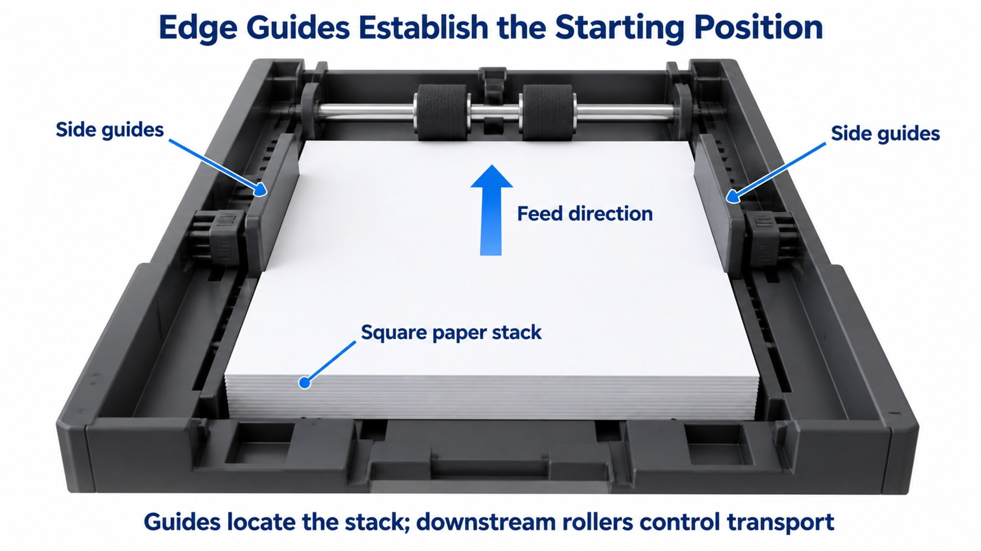
Figure 1. Side guides establish the paper stack's initial position. Downstream rollers and registration mechanisms control subsequent transport. Conceptual illustration.
How Do Rollers Move Paper Without Turning It Sideways?
The transport must provide the intended movement across the sheet width while controlling unwanted differences in contact and drag.
Feed rollers transfer motion through contact with the paper. Opposing pressure rollers provide the normal force needed at the nip—the region where the rollers meet around the sheet.
In a straight-feed section, unintended differences in effective surface speed or slip between contact positions can rotate the sheet. The result depends on roller diameter, tread deformation, surface condition, pressure distribution and resistance elsewhere in the path. Deliberately steered registration systems use controlled differences for correction; ordinary transport sections should not introduce them accidentally.
A shared shaft makes rollers rotate at the same angular speed, but different effective diameters can still produce different surface speeds. A stable shaft and repeatable tread geometry therefore matter alongside the drive motor.
The paper path must also accommodate handoff between roller pairs. If one pair pulls while another resists in an unintended direction, alignment can deteriorate after an initially successful pickup. Our explanation of how a printer paper feed system works places pickup, separation and transport in that wider sequence.
How Do Registration Rollers Correct Paper Skew?
One registration method squares the sheet's leading edge against a temporarily stopped roller nip before releasing it.
In this arrangement:
- Upstream rollers advance the sheet towards the stopped registration nip.
- The leading corner that arrives first meets the nip.
- A controlled additional feed forms a small buckle upstream and allows the other corner to reach the same reference.
- The registration rollers start at the required time and convey the squared sheet onwards.
The background discussion in Canon's sheet-conveying patent US8540240B2 describes this stopped-nip method and its limitations. The patent's proposed arrangement adds controlled reverse rotation; the simplified illustration below shows the basic stopped-nip principle, not that complete design.
The sheet needs room and suitable flexibility to respond. Feed amount, nip geometry and release timing must be designed together. This is controlled registration, not a recommendation to force paper against a blocked path. Nor does squaring the leading edge automatically establish the correct lateral position.
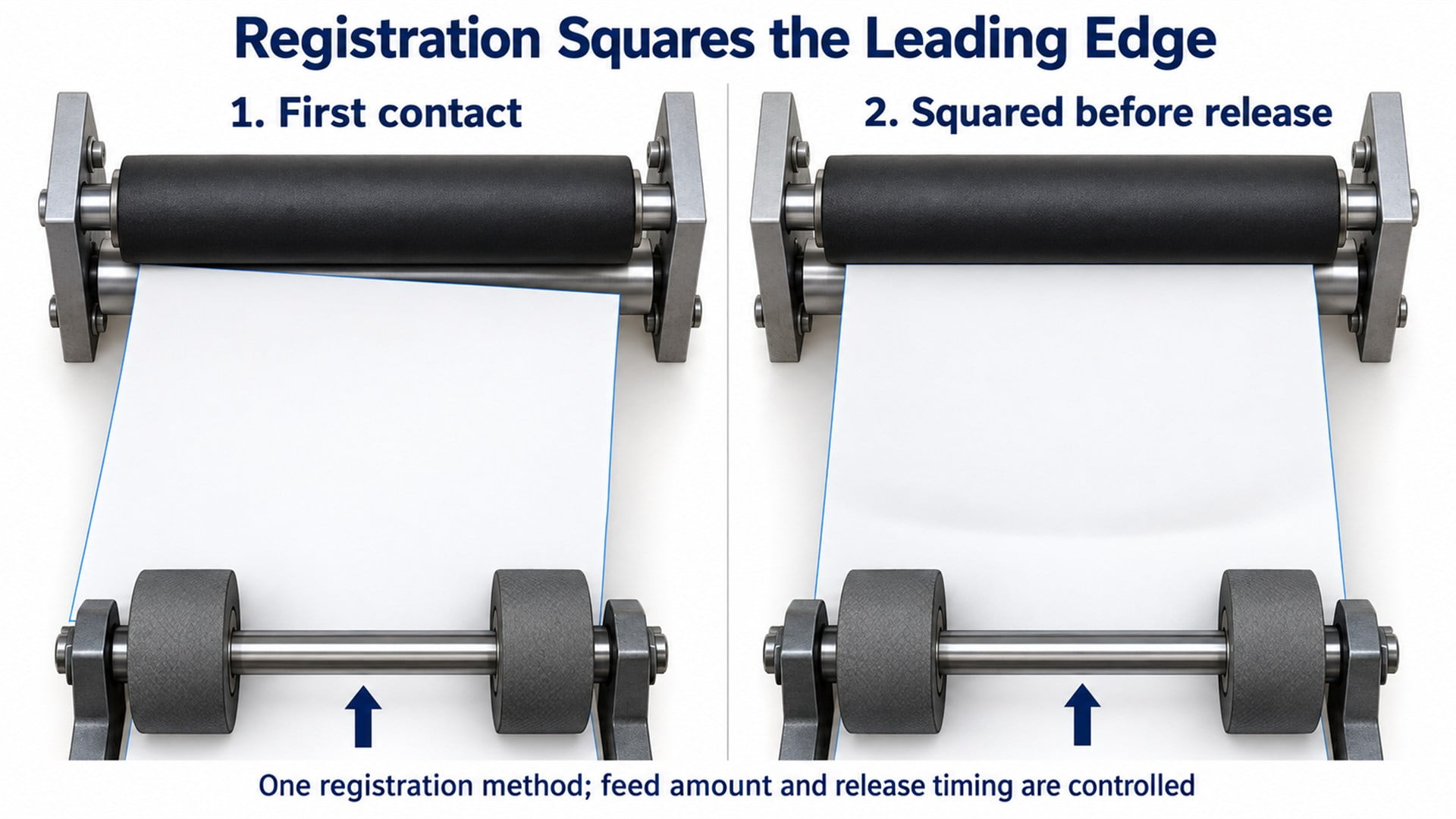
Figure 2. One mechanical registration principle: the leading edge squares against a stopped nip before release. Actual roller layout and control depend on the printer.
What Do Paper Sensors Contribute?
Sensors provide position information; drives and registration mechanisms perform the correction.
A paper-presence sensor can indicate that a sheet has reached a location. That signal alone does not establish its angle or lateral position. More detailed registration requires an appropriate arrangement of sensors and controlled motion.
Xerox's sheet-registration patent US6634521B1 describes leading-edge and side-edge measurements together with independently driven, steerable nips. In that design, the controller uses measured sheet position and orientation to command corrective motion. This demonstrates a different approach from simply stopping the leading edge at a nip; it does not establish that every printer uses active steering.
For component selection, the important boundary is what the control system can observe and adjust. A sensor cannot remove mechanical play, and a bearing cannot determine when a sheet should enter the imaging stage. Both must operate within the equipment's defined requirements.
Why Do Bearings, Axles and Brackets Matter to Alignment?
They help preserve the roller's intended position and rotation under operating load.
A roller may turn around a fixed axle on internal bearings, or rotate together with a shaft supported by bearings in the frame. The arrangement determines which parts must be located and which must remain free to rotate. Some printer mechanisms use bushings instead of rolling bearings.
The load path includes the roller surface, wheel or hub, bearing or bushing, axle or shaft, bracket and frame. Excessive movement at any interface can change the contact condition. An unsuitable clamping arrangement can also increase resistance or trap a rotating part against an adjacent face.
For alignment, I would assess the assembly under its representative load. A bearing's catalogue accuracy does not establish the runout of the finished wheel, the straightness of a shaft or the parallelism of its brackets.
| Functional feature | What it influences | Useful drawing or inspection information |
|---|---|---|
| Running surface relative to the rotation axis | Repeatability of contact through a revolution | Runout datum, measurement location and acceptance limit |
| Roller diameter and tread condition | Effective surface speed and contact behaviour | Functional diameter, material grade and measurement condition |
| Bearing seats and retention | Ring location and assembled rotation | Fits, retaining features and intended clamping path |
| Axial clearance and mounting width | Unwanted side contact or excessive end movement | Spacers, shoulders and assembly clearance |
| Shaft support and bracket geometry | Position of the nip relative to the paper path | Support span, reference surfaces and alignment requirements |
Tight tolerances should serve these functions. Making an unrelated cosmetic surface more precise will not correct a poorly located bearing seat.
Where Can HUNE Bearing Rollers Fit into Printer Mechanisms?
An integrated bearing wheel is relevant when its surface, support and mounting arrangement match a specific rolling function.
HUNE's flat roller wheels with integrated bearings provide examples of a polymer running surface combined with a bearing core. Such a structure can be assessed for a compatible passive idler or mechanical guide position in printer equipment.
The contact task must be explicit. A wheel running against a rigid guide needs matching geometry and clearance. A wheel touching paper needs additional assessment of pressure, traction, marking and the paper surface. A hard polymer bearing wheel is not automatically interchangeable with a compliant rubber feed roller.
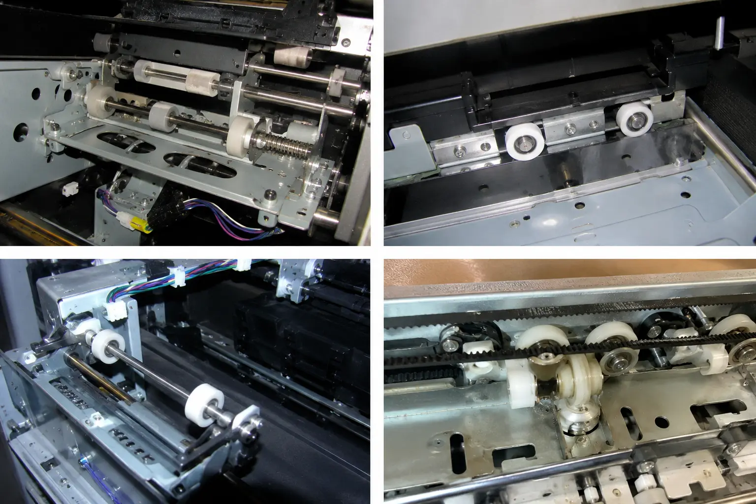
Figure 3. Printer mechanism examples from HUNE's existing media library. These images show component arrangements, not measured paper-alignment performance or a universal replacement specification.
For a custom wheel, define the functional surfaces before choosing a manufacturing route. A machined sample may establish fit, while moulded production needs separate confirmation of material and dimensional consistency. The comparison of POM roller machining and injection moulding explains those choices in more detail.
What Should an OEM Buyer Send the Roller Supplier?
Send the roller requirements in the context of the paper path, rather than requesting a wheel from diameter alone.
A useful enquiry includes:
- The component's role: driven feed roller, registration contact, passive idler or mechanical guide wheel.
- Mating geometry: axle or shaft drawing, bearing seats, spacers, bracket and the opposing roller or guide profile.
- Paper requirements: sizes, thickness range, coatings, stiffness-related constraints and permitted surface marking.
- Operating conditions: load directions, nip force where known, speed, starts, reversals and environment.
- Critical acceptance criteria: running geometry, assembly clearance and the equipment's skew, lateral-position and registration targets.
- Supply scope: material grade, bearing specification, prototype quantity, annual demand, inspection and assembly content.
Unknown values should be identified for the equipment designer to resolve, rather than replaced with guessed tolerances or loads.
Validate geometry first, then assess production-representative assemblies in the actual path. Trials should cover relevant paper types, widths and feed conditions, including duplex operation where required. A pilot lot should confirm that the intended manufacturing process can reproduce the approved component. A successful loose-wheel rotation check is only one small part of that assessment.
Frequently Asked Questions
Is paper alignment the same as printhead alignment?
No. Paper alignment concerns the sheet's physical position and orientation during transport. Printhead alignment concerns how an inkjet printer places ink from its printheads or nozzle groups. The two can affect the appearance of a print, but they address different parts of the system. A printhead alignment routine does not establish whether the paper guides and transport rollers hold a sheet square.
Why does double-sided printing need its own alignment assessment?
Duplex printing sends the sheet through another transport sequence before the second side is printed. That sequence can introduce additional positioning variation. The first printing pass may also change the sheet's condition, depending on the process. The front-to-back result therefore needs assessment with representative media and the intended duplex path, rather than being inferred from single-sided transport alone.
Does thicker paper always stay better aligned?
No. Greater stiffness can help a sheet resist some deformation, but it can also change how the sheet negotiates curves, enters a nip or responds to a registration buckle. Thickness alone does not fully describe stiffness, surface friction or coating behaviour. Roller pressure and path geometry must suit the specified media range rather than assuming that heavier stock is automatically easier to control.
Can a precisely made roller guarantee correct image margins?
No. Image margins also depend on sheet dimensions, lateral registration, arrival timing and the printing system's image placement. A precise roller helps reproduce its intended contact and motion, but it cannot determine all those variables. OEM approval should connect component measurements with an installed transport assessment and a defined image-to-edge requirement for the complete printer.
Discuss a Custom Printer Roller with HUNE
HUNE manufactures sliding rollers, plastic bearing wheels and hardware components for OEM applications. Its sliding rollers with bearing range offers structures to compare when a printer mechanism needs a compact rolling support or guide.
For a paper-alignment project, first identify whether the requirement concerns skew, lateral location or arrival timing. Then define the roller's contact function and the mating assembly that maintains its position.
To review a suitable component, send HUNE your printer roller enquiry with the roller and mating-part drawings, paper or guide details, load direction, speed, critical dimensions and expected quantity. Use those requirements to agree on a sample specification and an installed validation plan before production.


