

Most stack-fed printers use a pickup roller to move paper towards a separation mechanism. A friction pad or controlled retard roller holds back unwanted sheets while the feed roller advances the intended sheet. Downstream rollers then take over transport. The process depends on contact forces, paper properties and timing—not simply a fixed opening that is exactly one sheet thick.
Moving the top sheet and preventing the next sheet from following are separate jobs. The pickup roller can start both sheets moving because adjacent sheets transmit frictional force to one another. Separation is what turns that initial movement into individual-sheet feeding.
This article explains common top-feed friction mechanisms and the implications for roller, bearing and mounting selection. It does not assume every printer uses the same feeder layout.
What Happens Between the Paper Stack and the Print Path?
The feeder presents the stack, picks paper, separates it and transfers the selected sheet downstream.
A typical sequence is:
- Present the paper: The tray or lift mechanism keeps the upper part of the stack within the pickup mechanism's working range.
- Start movement: A pickup roller applies traction to the top sheet and moves its leading edge towards the separator.
- Restrain extra sheets: A pad or separation roller opposes unwanted lower-sheet movement.
- Hand off the selected sheet: Transport rollers carry it towards registration and the printing section.
- Prepare the next cycle: The drive and control arrangement prevents uncontrolled continued pickup while the current sheet progresses.
Some designs combine pickup and feeding functions in one roller; others use separate components. The location of a wheel in the mechanism therefore matters more than its name in a parts list.
For the complete path beyond separation, our explanation of how a printer paper feed system works covers the relationship between feeding, registration and transport.
Why Does the Pickup Roller Not Simply Grab Only the Top Sheet?
The roller contacts the top sheet, but that sheet can drag another sheet with it.
Paper is not a set of perfectly independent layers. Contact between sheets, their surface condition and the way the stack is presented affect how they move. The pickup mechanism needs enough traction to start feeding, yet that does not establish that only one sheet has entered the next stage.
I would first separate two requirements in an OEM review: sufficient pickup force and effective rejection of extra sheets. Increasing pickup pressure without reviewing separation can change several contact forces at once. It should not be treated as a universal improvement.
Stack position also changes as sheets are consumed. The tray support, pickup arm and any lift control must preserve the intended contact condition across the specified stack range. A feeder that works with a nearly full tray still needs evaluation near the lower end of that range.
How Does a Separation Pad Hold Back Extra Sheets?
A friction pad resists lower-sheet movement while the feed roller provides enough traction to advance a single sheet.
The pad sits opposite the feeding surface. With one sheet present, the roller must overcome the pad's resistance. If two sheets enter, the pad acts on the lower sheet while the roller acts on the upper one.
In the simplified design model discussed in European Patent Office publication EP1721846B1, the separating force falls between the available driving force and the force transmitted between sheets. Too little restraint permits multiple feeding; too much can prevent normal feeding. This is a force relationship, not a universal friction value or spring setting.
The patent explains a particular separator design. Its background is useful for understanding why pad material, nip force and media must be considered together; it does not prove performance for a proposed OEM assembly.
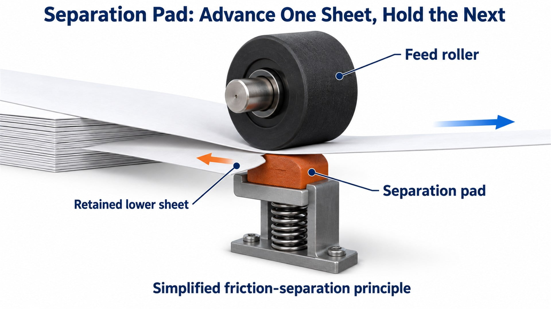
Figure 1. Simplified pad separation. Paper-layer spacing is exaggerated for visibility; the mechanism does not rely on a rigid one-sheet-thickness slot.
How Does a Retard Roller Separate Two Sheets?
A retard roller applies controlled resistance rather than behaving like a freely turning idler.
In one common arrangement, the lower roller receives reverse drive through a torque limiter. Its behaviour changes with the contact condition:
- One sheet enters: Traction through the sheet can overcome the limited opposing torque, allowing the retard roller to follow the forward-moving sheet.
- Two sheets enter: The sheet-to-sheet interface transmits less force than the designed separating action. The lower roller restrains or returns the extra sheet while the upper feed roller advances the top one.
Canon's separation-roller patent application US20190270603A1 describes this distinction. It also identifies a passive alternative using a separation roller coupled through a torque limiter to a fixed shaft. Reverse drive is therefore one architecture, not a feature to assume for every separation roller.
The limiter, roller surface and contact load form a matched system. Specifying only the wheel diameter leaves the separating behaviour undefined.
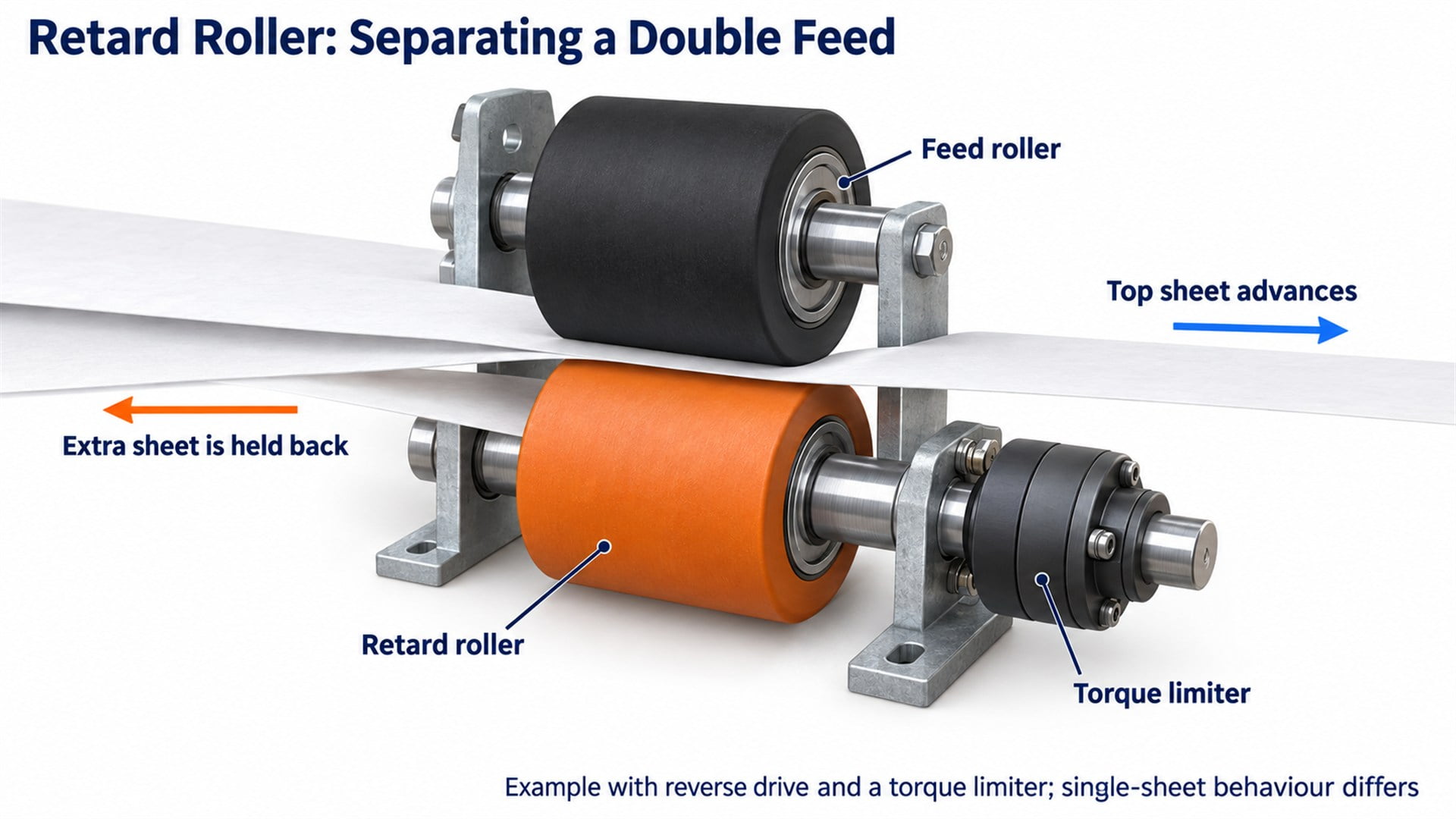
Figure 2. A reverse-driven retard arrangement during double-sheet entry. Its single-sheet behaviour differs; the drawing is a conceptual illustration.
What Happens After One Sheet Has Been Separated?
Downstream transport must accept the sheet without disturbing the remaining stack or creating an unintended pull between stages.
The selected sheet may still be in contact with the feeding section when its leading edge reaches another roller pair. The drive arrangement must accommodate that overlap.
Depending on the design, pickup can be disengaged, lifted or allowed to overrun through an appropriate mechanism. Timing and the relationship between stages matter: a sheet should not be forced to follow incompatible motions at two contact points.
Registration then addresses a different problem—positioning the selected sheet for printing. A feeder can successfully separate one sheet and still deliver it at an angle. Likewise, correcting the leading-edge position does not establish that a second sheet was excluded upstream.
For procurement, define the handoff requirement as part of the assembly duty. A roller supplied for intermittent pickup may have different drive and overrunning requirements from a continuously driven transport roller.
Why Do Paper and Tray Conditions Change Separation?
The feeder operates on real media, so stack geometry and material condition belong in the specification.
Paper thickness alone does not describe stiffness, surface coating, curl or sheet-to-sheet behaviour. The intended media range should identify these characteristics where they affect the feed mechanism.
The tray must also locate the stack while permitting the selected sheet to leave it. Epson's paper-loading documentation specifies stack-loading limits and guides that contact paper without excessive tightening. These are model-specific instructions, but they illustrate the relationship between media presentation and feeding.
For an equipment project, I would request representative media samples and the permitted stack-height range before approving a paper-contact roller. A successful trial with one paper grade does not establish compatibility with coated stock, a different stiffness range or a different tray condition.
Acceptance should also distinguish no-feed, multiple-feed, skew and surface marking. Combining them into one vague requirement such as “smooth feeding” makes it difficult to identify what a sample actually demonstrated.
What Role Do Bearings Play in Single-Sheet Feeding?
Bearings support rotating parts; they do not automatically provide the resistance needed for separation.
A bearing, a one-way clutch and a torque limiter serve different functions:
- A bearing supports relative rotation and transfers loads into the shaft or housing.
- A one-way clutch allows or transmits motion according to the direction and arrangement.
- A torque limiter restricts transmitted torque according to its design.
These functions may be packaged close together, but they are not interchangeable. Replacing a controlled separation assembly with a freely rotating bearing wheel can remove the very action that holds extra sheets back.
The complete support path includes the tread, hub, bearing or bushing, axle or shaft, spacers, retaining features and bracket. The drawing should show which parts rotate and which surfaces receive the clamping force.
I would assess running resistance and clearance after assembly. A wheel that spins freely on the bench can bind when its mounting faces or spacers load the wrong components. Conversely, low bearing resistance cannot compensate for an unsuitable paper-contact surface or an incorrect separating torque.
Where Can HUNE Bearing Rollers Fit into Printer Equipment?
Integrated polymer bearing wheels are structures to consider for compatible guides or passive supports within a printer mechanism.
HUNE's flat roller wheels with integrated bearings combine a polymer running surface with a bearing core. This construction can be reviewed where the equipment needs a compact rolling contact against a mating guide or a defined passive support interface.
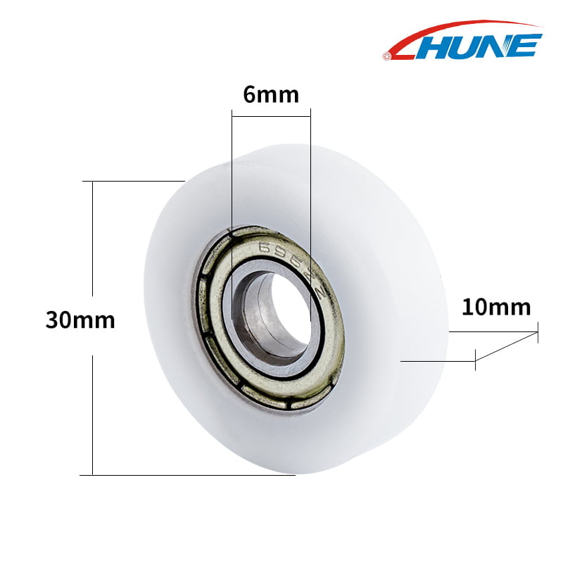
Figure 3. An existing HUNE bearing-roller product image. The dimensions describe the illustrated component, not a universal printer or separator specification.
For direct paper contact, assess material, pressure and marking separately. A hard polymer bearing wheel is not automatically a substitute for an elastomer pickup roller, a separation pad or a torque-controlled retard assembly.
That distinction helps keep an enquiry precise: identify whether the requested component guides a mechanical part, supports paper passively or performs a driven separation function before choosing a catalogue structure.
What Should an OEM Buyer Put on the Roller Drawing?
Control the functional interfaces and state the drive behaviour that the component must support.
| Drawing or enquiry item | What to define | Why it matters |
|---|---|---|
| Running surface | Contact width, profile, material grade and surface requirements | Determines interaction with paper or the mating guide |
| Rotation reference | Shaft or bearing datum and allowable assembled runout | Connects inspection to the actual running axis |
| Mounting | Bearing seats, retention, spacers and axial clearance | Controls fit and avoids unintended side contact |
| Loading | Force direction, contact load, support spacing and operating sequence | Establishes the duty of the wheel and support structure |
| Drive function | Driven, free-running, overrunning or torque-controlled arrangement | Prevents substitution of mechanically different assemblies |
| Validation | Media range, stack conditions and separate acceptance criteria | Defines what sample approval must demonstrate |
Send the mating-part drawings, prototype quantity, expected annual demand and supplied assembly scope as well. State unknown requirements explicitly so the equipment designer can resolve them rather than asking the supplier to guess.
For custom polymer geometry, compare prototype and production routes against the functional dimensions. Our discussion of POM roller machining and injection moulding explains why a machined fit sample and a moulded production part require separate process assessment.
Approve geometry first, then test production-representative assemblies in the intended mechanism. Evaluate the media and stack conditions that matter to the project, followed by a pilot lot to check repeatability. One successful sample should not be presented as proof of a service-life or multiple-feed rate that has not been measured.
Frequently Asked Questions
Does the printer use a gap exactly one sheet thick?
Not in the common friction-separation mechanisms described here. The paper passes through a compliant contact region where drive and restraining forces determine which sheet advances. A fixed slot alone would not accommodate the range of media thickness and deformation that a feeder may need to handle. Clearances still matter, but they are part of a larger mechanical design.
Is a retard roller always turning backwards?
No. In a reverse-driven arrangement with a torque limiter, a single sheet can cause the retard roller to follow its forward movement. When extra sheets enter, the lower sheet can be restrained or returned. Passive resistance arrangements also exist. Identify the mechanism and operating state before assuming a particular rotation direction from the name of the component.
Does a paper sensor perform the separation?
The physical separator performs the separation in these mechanisms. Sensors may monitor arrival, timing or other conditions and allow the controller to respond. A basic sheet-presence sensor does not necessarily distinguish one sheet from two overlapping sheets. Detection capability and corrective action should be specified separately from the roller and pad functions rather than assumed from the presence of a sensor.
Is a separation roller the same as a registration roller?
No. Separation controls how many sheets proceed from the supply. Registration controls the position or timing of a selected sheet before printing. The two functions may be located close together, but they solve different problems. A parts enquiry should state the component's role and operating behaviour, because a similar-looking roller may belong to a different stage of the paper path.
Discuss a Printer Roller Component with HUNE
HUNE manufactures sliding rollers, plastic bearing wheels and hardware components for OEM applications. Its sliding rollers with bearing range provides structures to compare for suitable rolling guides and support positions in equipment.
For a single-sheet feeder project, first distinguish pickup, separation and downstream transport. Then identify the roller surface, support arrangement and any clutch or torque-control function required at that position.


