

A pulley wheel with a bearing is usually the better choice for frequent rotation, higher speed, low and repeatable running torque, or tighter control of wobble. A plain-bore pulley is often the better OEM choice for light loads, low speed, intermittent movement, compact packaging and aggressive unit-cost targets. A third option—a pulley with a separate sleeve bushing—sits between these two structures and should not be treated as identical to a plastic wheel running directly on a pin.
I would not choose from wheel diameter or purchase price alone. The correct decision depends on the pulley’s duty cycle, shaft diameter and finish, contact pressure, environment, allowable play, bracket geometry and the belt, cable or rail touching the outer profile. The complete load path determines whether the simpler bore remains reliable or a rolling bearing adds real system value.
What Is the Structural Difference?
A bearing pulley rolls internally on raceways and balls; a plain-bore pulley slides at the wheel-to-shaft interface.
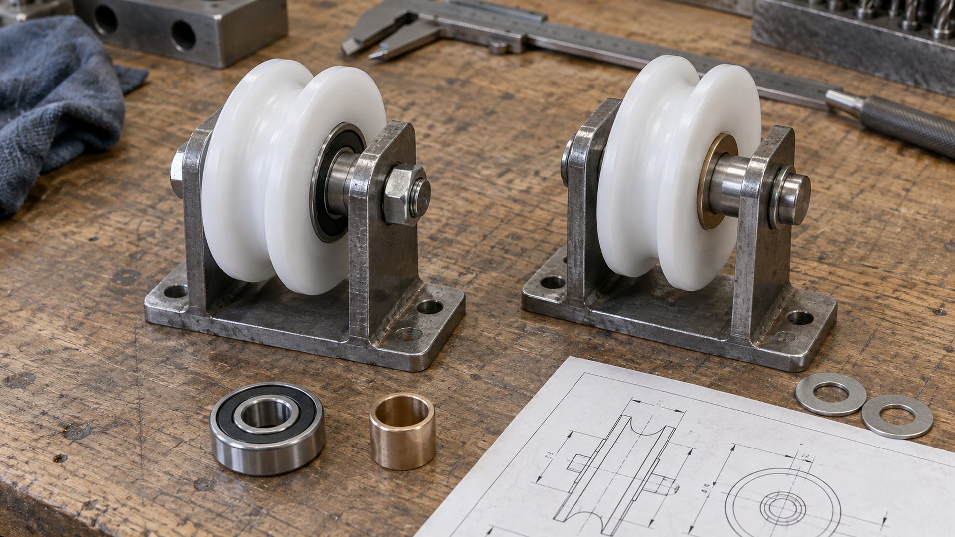 The two structures may share the same outer profile, but their rotating interfaces, shaft requirements and assembly controls are different.
In a compact bearing pulley, a ball bearing is pressed into, molded into or mechanically retained inside the wheel. The axle normally supports the bearing inner ring while the wheel rotates with the outer ring. Seals or shields may retain grease and limit contamination. The running interface is formed by rolling elements and precision raceways.
In a direct plain-bore pulley, the molded or machined wheel bore rotates on a metal or polymer pin. Sliding occurs across that cylindrical interface. The wheel material, bore quality, shaft finish and running clearance therefore act as the bearing system.
A bushed pulley adds a distinct sleeve between wheel and shaft. That sleeve may be a self-lubricating polymer, a metal-polymer composite or another engineered bearing material. It can provide more predictable wear behavior and protect the wheel hub, but only when its material, wall thickness, housing fit and shaft are designed together.
The load paths are:
- Bearing pulley: belt, cable or rail → wheel profile → wheel hub → bearing outer ring → rolling elements → inner ring → axle → bracket.
- Plain-bore pulley: belt, cable or rail → wheel profile → wheel hub and bore → shaft → bracket.
- Bushed pulley: belt, cable or rail → wheel profile → wheel hub → bushing → shaft → bracket.
For more detail on the rolling interface itself, our guide to how bearings reduce friction explains the difference between sliding and rolling contact without treating the bearing as an isolated component.
Which Structure Is Better for an OEM Project?
Use a bearing pulley when duty and motion quality justify its extra parts; use a plain bore when the application is slow, intermittent and tolerant of a sliding interface.
| Decision factor | Pulley wheel with bearing | Direct plain-bore pulley | Pulley with sleeve bushing |
|---|---|---|---|
| Starting and running torque | Usually lower and more repeatable | Usually higher and more sensitive to material pair and fit | Can be controlled with a specified bearing material |
| Continuous or frequent rotation | Usually favored | Requires careful wear and heat evaluation | Possible within the bushing supplier’s limits |
| Low-speed intermittent movement | Often more capability than needed | Often a practical solution | Useful when direct wheel material is unsuitable |
| Shaft requirement | Bearing-seat fit, shoulder and clamp control | Shaft diameter, finish, hardness and corrosion condition are functional | Shaft and bushing recommendations both apply |
| Radial and axial play | Bearing clearance plus fits and assembly stack | Determined mainly by bore clearance, wear and end control | Determined by bushing clearance, fit and end control |
| Contamination | Seals help, but drag and seal suitability matter | Simple structure; abrasive particles can wear bore and shaft | Material and debris-embedding behavior matter |
| Part and assembly count | Higher | Lowest | Between the two |
| Initial unit cost | Usually higher | Usually lower | Material and insertion step add cost |
| Service behavior | Bearing can sometimes be replaced | Wheel or pin may be replaced as a pair | Bushing may protect the wheel and shaft |
This table is a screening tool, not an automatic selection rule. A small sealed bearing can perform poorly if a nut clamps the rotating ring, while a correctly designed plain polymer bore can provide long service in a slow guide mechanism. Conversely, a plain bore selected only because it is cheap may develop torque variation, dust or play when the cycle count rises.
When Should an OEM Choose a Pulley Wheel With a Bearing?
A bearing pulley becomes valuable when low friction must remain consistent across many rotations and production units.
I normally move toward a bearing structure when several of the following conditions occur together:
- the pulley rotates continuously or cycles frequently;
- the surface speed is high enough for sliding heat and wear to become a concern;
- starting force is part of the product’s user experience or control-system requirement;
- the mechanism uses a small motor with limited torque margin;
- wheel wobble or radial movement affects tracking;
- the pulley is difficult to access after assembly;
- a wider wheel, offset groove or cantilevered load creates a meaningful moment;
- the customer requires repeatable running torque from batch to batch; or
- the shaft cannot be treated as a renewable wear component.
Rolling bearings have standardized basic dynamic and static load ratings. These ratings help engineers calculate bearing fatigue and permanent-deformation risk under defined conditions. The NSK explanation of dynamic load ratings and fatigue life also makes clear that speed, applied load and the actual bearing arrangement are part of selection.
However, a catalog bearing rating is not the load rating of the finished pulley. The system may be limited first by:
- polymer tread creep or cracking;
- loss of bearing retention in the hub;
- groove contact stress;
- axle bending;
- bracket deflection;
- over-tightened fasteners;
- persistent flange contact;
- seal torque at low temperature; or
- contamination at the belt, cable or track interface.
For example, a bearing can rotate smoothly on a test pin while the complete bracket assembly binds because two side plates are not parallel. I therefore check bearing calculations and the assembled pulley separately.
HUNE’s U-groove bearing pulley wheels show a common integrated approach for cable, round-rail and guide applications. The groove still has to match the mating diameter and contact condition; adding a bearing does not correct a poor profile.
Where the mating surface is flat and lateral guidance comes from another feature, flat roller wheels with integrated bearings illustrate a different tread geometry. The profile choice and the hub structure are separate decisions.
When Is a Plain-Bore or Bushed Pulley the Better Choice?
A plain-bore design is often the better value when motion is slow and intermittent, the load is modest, and the wheel-shaft pair can be controlled.
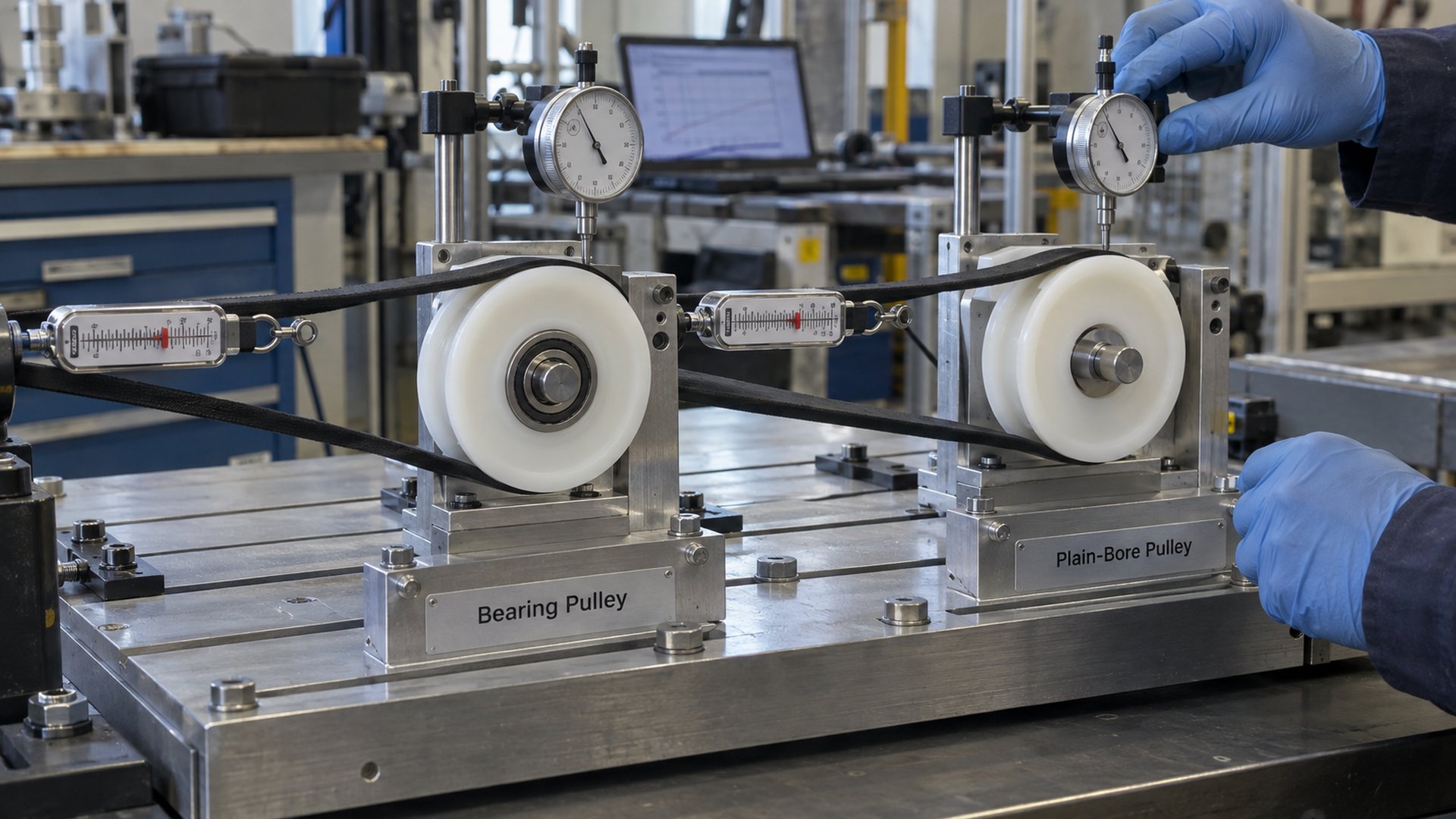 This HUNE media-library image shows a bearing-free positioning roller with an integrated inner plastic layer rather than a steel rolling bearing.
Suitable applications can include furniture positioning wheels, light guide rollers, dampers, linkages, small access panels and mechanisms that only move through a short travel occasionally. The simple construction can reduce radial package size, part count and assembly steps.
The HUNE bearing-free plastic positioning roller is one example of a dual-material wheel intended for light-duty guidance. It should not be generalized into a universal replacement for bearing pulleys. Its function comes from the complete material and geometry combination.
A separate bushing is worth considering when the wheel needs one material at the outer tread but another material at the shaft interface. It may also be useful when the OEM wants a replaceable wear surface, more predictable tribological data or better resistance to a particular chemical environment.
Plain bearings can carry high pressure in compact space, but pressure alone does not establish suitability. Sliding speed produces frictional heat. The product of contact pressure and surface speed—often called the PV value—is commonly used as one screening parameter for plain-bearing materials. The igus plain-bearing technical data explains that actual PV performance also depends on shaft material, ambient temperature and operating time. Manufacturer limits are material-specific; a generic “plastic” PV limit is not technically valid.
I would be cautious with a direct plain bore when the product requires long continuous rotation, very low drive torque, tight positioning accuracy, little allowable wear, or stable performance over a wide temperature range. A bushing or rolling bearing may then produce a more controllable design.
How Do Friction and Speed Change the Decision?
A bearing reduces friction at the axle interface, but total pulley resistance also includes seals, grease, profile contact and alignment.
For a direct plain bore, sliding velocity occurs at the shaft diameter. A larger wheel does not by itself reduce the shaft-interface speed if the shaft diameter and rotational speed remain unchanged. Engineers should distinguish:
- outer tread speed where the wheel contacts a belt, cable or rail;
- rotational speed of the pulley;
- sliding speed at the bore or bushing diameter; and
- starting torque under load after storage.
Plain-bore torque varies with load, friction coefficient and effective shaft radius. The friction coefficient is not a fixed property of “POM on steel” or “nylon on steel.” It changes with surface finish, humidity, temperature, lubrication, contamination, pressure and speed.
Bearing-pulley torque includes rolling contact, seal drag and lubricant shear. A contact seal can protect a bearing but add resistance, especially in small mechanisms. Shielded bearings generally produce less seal contact, yet offer a different contamination barrier. The correct structure depends on what the environment actually contains.
The belt, cable or rail can dominate system resistance. A misaligned cable rubbing a flange may consume more force than either bearing option. A soft outer tread can deform under load. A crowned or grooved profile can improve tracking, but an incorrect profile can create edge contact and heat.
For these reasons, I compare complete assembled starting force and steady running force. A free-spinning hand test without the real mating component cannot represent the mechanism.
How Do Load, Shock and Duty Cycle Change the Decision?
Load magnitude matters, but load direction, duration, impact and lever arm often decide which structure survives.
For a plain bore, projected bearing pressure is normally evaluated across the shaft diameter multiplied by the effective contact length. Edge loading from a bent pin, tilted bracket or short hub can invalidate the assumed uniform pressure. A longer bore may distribute pressure, but it also demands better coaxiality and can bind more easily when the bracket distorts.
For a bearing pulley, engineers calculate the equivalent bearing load and required life, then verify the hub, axle, retention and bracket. The bearing may tolerate radial load but still experience unwanted axial force from belt skew or flange rubbing. A narrow single bearing also provides limited resistance to an external overturning moment.
Shock is not automatically an argument for either design. A polymer bore may tolerate occasional dirt or impact without brinelling a raceway, while a rolling bearing may control motion better after repeated cycles. The outcome depends on the impact energy, support stiffness, material, clearance and failure criterion.
The duty description should include:
- maximum and normal radial load per pulley;
- any axial load or moment from an offset contact line;
- continuous rotation, oscillation or intermittent indexing;
- speed, travel length and cycles per day;
- dwell time under load;
- acceleration, stops and impact events; and
- required life or allowable wear at end of test.
How Do Dust, Moisture and Chemicals Affect Selection?
Environmental resistance depends on the entire material and sealing system, not on the words “bearing” or “plain bore.”
A sealed bearing can keep grease in and limit entry of common contaminants, but it is not automatically waterproof or chemically resistant. Bearing steel, seal elastomer, grease, axle and hub material must all suit the exposure. Corrosion on the inner ring or shaft can disturb fits even when the rolling surfaces remain protected.
A plain polymer bore removes raceways and grease, which can simplify washdown or clean mechanisms. Abrasive dust can still enter the clearance, score the shaft and enlarge the bore. Moisture can change dimensions of moisture-sensitive polymers, while chemicals may swell or embrittle a material.
The shaft is particularly important. SKF’s composite dry sliding bearing catalogue notes that counterface material and surface finish should be selected from load, motion and environmental conditions, and that corrosion scars increase roughness and abrasive wear. Its values apply to the listed SKF composites, but the principle is useful for any bushed pulley: specify the counterface instead of treating the shaft as generic hardware.
For outdoor, food-contact, medical or clean equipment, the supplier also needs the applicable regulatory and cleaning requirements. Material compliance does not prove mechanical suitability, and mechanical suitability does not prove compliance.
Which Functional Dimensions Should the Drawing Control?
The drawing must control the rotating interface and mating profile, not only outside diameter, width and bore.
For both designs, I would define:
- functional running diameter;
- groove radius, angle, width and depth, where applicable;
- face width and flange geometry;
- concentricity or runout between running surface and rotating bore/axis;
- total wheel width and bracket-side clearances;
- axle position relative to mounting features;
- allowable axial movement; and
- critical material and environmental requirements.
For a bearing pulley, add:
- exact bearing designation and internal clearance where required;
- open, shielded or sealed construction;
- hub seat diameter, form and retention method;
- which ring is clamped and which ring rotates;
- shoulder, spacer and washer geometry;
- axle fit and surface condition; and
- maximum tightening condition for the assembly.
For a direct plain bore or bushed pulley, add:
- finished bore diameter, roundness and cylindricity as needed;
- shaft diameter, tolerance, material, hardness and finish;
- effective bearing length;
- installed running clearance across temperature extremes;
- bushing housing fit and installed inside diameter;
- thrust washer or end-face contact arrangement; and
- lubrication condition: dry, initial lubrication or periodic lubrication.
Do not copy a tolerance from a ball-bearing seat onto a molded plain bore. The two interfaces need different fits and account differently for molding shrinkage, moisture and thermal expansion. HUNE’s roller materials and process overview can help buyers discuss POM, nylon, PU, metal parts and molding choices before final drawing approval.
How Should an OEM Compare Cost?
Compare cost per acceptable assembled mechanism, not only the wheel quotation.
A plain-bore wheel may remove the bearing, bearing-retention feature and bearing insertion step. It can also require a better shaft, an added washer, tighter coaxiality or replacement of both wheel and pin after wear. A bearing pulley costs more as a component but can reduce motor torque, variation, field access or service risk.
At high volume, the economic comparison should include:
- wheel and bearing or bushing cost;
- axle and shaft-finishing cost;
- molding or machining cycle;
- insertion, staking or retention operations;
- assembly time and error-proofing;
- inspection of running torque and runout;
- reject risk from fit variation;
- validation-test duration;
- expected service or replacement method; and
- supply continuity for the specified bearing or bushing.
I also check whether the design uses an established standard bearing or a highly specialized size. A custom bearing can solve packaging constraints but changes tooling, minimum quantity and supply risk. A molded direct bore may be commercially attractive only after the production volume supports suitable tooling and process control.
How Should an OEM Validate the Final Choice?
Validate both candidates in the real bracket and with the real belt, cable or rail whenever the decision is close.
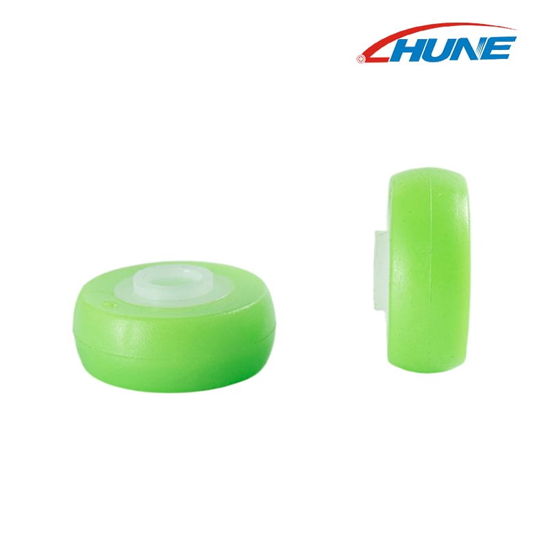 A useful comparison holds load, profile, alignment and environment constant while measuring the assembled systems.
A practical validation plan can compare:
- initial starting force and steady running force;
- torque variation through a full rotation;
- radial runout, axial movement and pulley tilt;
- belt, cable or rail tracking;
- temperature after the defined duty;
- noise under the actual load and enclosure;
- bore, shaft, tread and groove wear;
- performance after dust, moisture, temperature or chemical exposure; and
- dimensional change and functional force after the target cycle count.
The acceptance limit should come from the equipment requirement. A visible wear mark is not automatically failure, and a pulley that still rotates is not automatically acceptable. The real failure condition may be increased motor current, label-position error, cable damage, noise, excess play or loss of track alignment.
SKF’s bearing-selection principles emphasize that shafts, housings, fits, clearance, seals and lubrication are integral to a bearing system. The same system approach should be used when comparing a rolling bearing with a plain interface.
HUNE’s OEM development process describes drawing, material, tooling, sampling and validation considerations for custom rollers and molded components.
What Information Should a Buyer Send the Supplier?
A useful inquiry defines the mechanism and duty before asking the supplier to choose a bearing or plain bore.
Send the following information:
- application and the pulley’s function;
- 2D drawing or 3D model of the wheel, axle, bracket and mating part;
- belt, cable, rope, rail or track profile and material;
- available envelope and mounting method;
- normal and maximum load per pulley, including force direction;
- speed, travel, cycle frequency and dwell time;
- expected service life or validation cycle target;
- allowable starting force, running torque, noise and play;
- temperature, dust, water, humidity, chemicals and cleaning method;
- wheel, shaft and bracket material preferences;
- applicable regulatory or material-compliance requirements;
- annual volume, order quantity and tooling expectations; and
- existing samples, failure photos or measured wear if redesigning a current part.
If load or torque values are not yet known, send the equipment mass, number of pulleys, drive arrangement and motion profile. The supplier can then identify missing calculations instead of guessing from wheel diameter.
HUNE manufactures custom plastic-coated bearing rollers, pulley wheels, plain-bore plastic wheels, axles and metal brackets for OEM equipment and hardware systems. We can review the wheel profile, bearing or bushing structure, shaft, material and production method as one assembly. To discuss a new or replacement pulley, send HUNE your drawing, sample and duty conditions.
Frequently Asked Questions
Is a bearing pulley always smoother than a plain-bore pulley?
Not always at complete-system level. A suitable bearing normally lowers friction at the shaft interface, but seal drag, grease, excessive clamping, wheel deformation, track contact and misalignment can still raise running force. Compare the assembled mechanisms under load.
Can a plain plastic bore run without lubrication?
Some engineered polymer pairs are designed for dry running, while others need initial or periodic lubrication. Suitability depends on the exact wheel or bushing material, shaft material and finish, pressure, speed, temperature and environment. Do not assume every molded plastic bore is self-lubricating.
Does a pulley wheel with a bearing always carry more load?
No. Bearing ratings apply to the rolling bearing under specified conditions. The finished pulley can be limited by the wheel hub, tread, groove, axle, fastener or bracket. A compact plain bearing may also carry substantial pressure at low speed when correctly designed. Rate the complete assembly.
Which pulley type is quieter?
Noise depends on tread material, mating surface, runout, clearance, bracket resonance, speed and contamination. A bearing can reduce stick-slip at the shaft, while a polymer plain bore may avoid ball-pass or seal-related sound in a slow mechanism. Noise should be tested inside the actual equipment enclosure.
Practical Engineering Recommendation
Choose the simplest structure that can meet the measured duty with controlled margin and stable production.
For frequent rotation, limited drive torque, higher speed or tight motion control, start with a properly mounted bearing pulley. For light-load, slow and intermittent guidance, compare a direct plain bore and a specified sleeve bushing before accepting the cost and space of a rolling bearing. In either case, approve the design from the complete wheel–interface–axle–bracket–mating-surface assembly and validate it under the real load, alignment and environment before mass production.



[…] guide to bearing pulleys versus plain-bore pulleys explains the broader choice between rolling-element and sliding interfaces. A flanged bushing is […]