

A flanged bushing is a plain sleeve bearing with an enlarged rim at one end. The cylindrical sleeve supports radial load and provides the sliding surface around a shaft. The flange adds an axial locating face, helps stop the bushing from moving through the roller hub and can act as a thrust surface when the material and design are rated for that duty.
A roller should use one when it needs low-cost, low-speed rotation plus controlled side location, especially where a separate thrust washer or retaining shoulder would add parts. Typical candidates include light guide wheels, furniture rollers, positioning rollers and dusty mechanisms that benefit from dry-running polymer bushings. A flange is not automatically suitable for continuous or heavy axial load. The engineer must check radial pressure, sliding speed, flange pressure, shaft finish, housing fit, alignment, temperature and the mating side face as one system.
What Is a Flanged Bushing?
It combines a cylindrical plain-bearing sleeve with an integral flange at one end.
The sleeve fits into a roller hub, housing or bracket and runs against a shaft or pin. Depending on the assembly, the bushing may be fixed in the roller while the roller and bushing rotate around a stationary shaft. Another design may hold the bushing stationary while the shaft rotates. The relative motion must be defined before the fit and material are selected.
The flange extends beyond the sleeve outside diameter. It can perform three related functions:
- locate the bushing axially against one side of the hub;
- resist migration through the housing in one direction; and
- provide a wider sliding face for light or intermittent axial contact.
That third function needs qualification. A thin flange intended only for location should not be assumed to carry a continuous thrust load. The material supplier's design data, flange geometry and installed test should confirm the allowable duty.
ISO 4379:2024 covers dimensions and tolerances for cylindrical and flanged copper-alloy bushes in its stated size range. ISO 2795:2020 similarly includes dimensional ranges for flanged sintered bearings. These standards show that a flanged bush is an established plain-bearing form, but they do not define every polymer or composite roller bushing.
How Is a Flanged Bushing Different from a Straight Sleeve?
A straight sleeve controls the radial interface; a flanged bushing adds a built-in axial reference on one side.
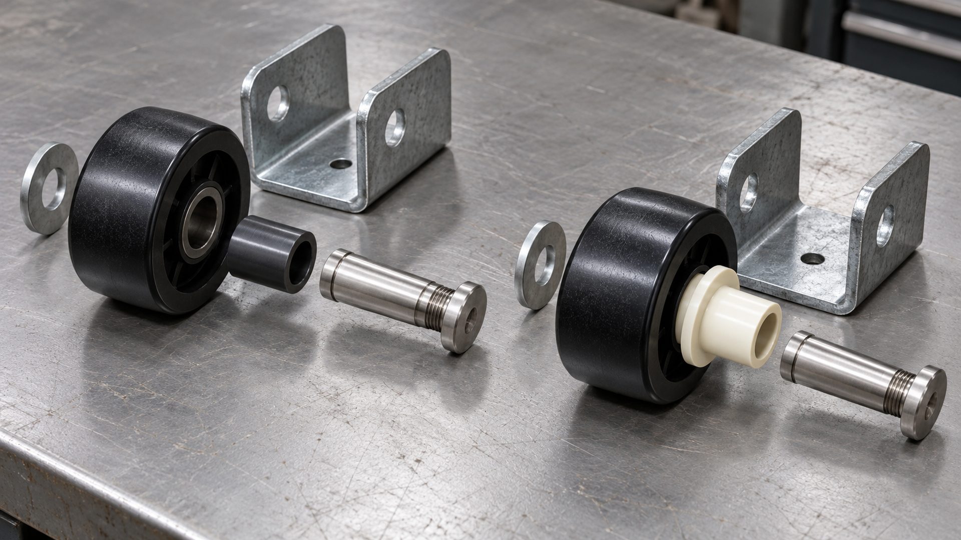 The flange can replace a separate locating washer or provide a controlled side-contact surface when the design supports it.
| Feature | Straight sleeve bushing | Flanged bushing |
|---|---|---|
| Radial sliding surface | Yes | Yes |
| Integral axial locating face | No | Yes, on the flanged side |
| Resistance to migration | Requires fit, shoulder or separate retention | Flange blocks movement in one direction |
| Thrust contact | Requires separate washer or shoulder | Flange may provide thrust face if rated |
| Required hub access | Can enter from either side if geometry allows | Must be inserted from the non-flanged side |
| Axial package | Compact sleeve only | Includes flange thickness and diameter |
A flange does not locate the roller in both axial directions by itself. The opposite side may use a second flanged bushing, a thrust washer, a wheel shoulder, a shaft shoulder or controlled bracket clearance. A double-flange or clip-in bushing is another option when capture from both sides is required.
What Is the Difference Between a Flanged Bushing and a Thrust Washer?
A flanged bushing integrates radial and one-sided axial sliding surfaces; a thrust washer handles only the axial face.
A straight bushing plus a separate thrust washer can perform a similar functional job. The separate arrangement gives the designer more freedom to choose radial and thrust materials independently. It may also simplify replacement if the side face wears faster than the bore.
The integrated flange reduces part count and prevents the thrust element from being omitted during assembly. It also fixes the relationship between the bore and the side face. That can help a small roller where the axial package and assembly time are limited.
The decision is not purely about part count. Compare:
- required thrust area;
- flange or washer thickness;
- wear on the bracket or shaft shoulder;
- ability to lubricate or run dry;
- replacement strategy;
- moulding and press-fit route; and
- tolerance stack across the bracket.
When Should a Roller Use a Flanged Bushing?
Use it when the roller needs both a radial sliding interface and a defined one-sided axial contact in a compact assembly.
Good candidates include:
- light guide wheels that occasionally touch a bracket side;
- furniture and cabinet rollers with modest speed and duty;
- positioning rollers that need a retained plastic insert;
- rollers that cannot accommodate a separate thrust washer;
- dry-running mechanisms where grease would attract dust;
- compact pulley or guide wheels with controlled side clearance; and
- assemblies where the flange simplifies manual or automated insertion.
I look for a clear reason for the flange. If the roller never sees axial displacement and the sleeve cannot migrate, a straight bushing may be simpler. If axial force is continuous or substantial, a dedicated thrust bearing, rolling bearing or larger thrust element may be more appropriate.
Our guide to bearing pulleys versus plain-bore pulleys explains the broader choice between rolling-element and sliding interfaces. A flanged bushing is one way to improve a plain-bearing architecture; it does not turn the roller into a ball-bearing roller.
How Does the Flange Handle Axial Contact?
The flange spreads axial force over an annular face, but its pressure and sliding speed must remain within the material's capability.
For an initial review, radial projected pressure on the sleeve is often considered as:
pᵣ = Fᵣ ÷ (d × L)
where Fᵣ is radial load, d is the shaft diameter and L is the effective sleeve length. The flange needs a separate axial review. A simplified nominal flange pressure is:
pₐ = Fₐ ÷ Aₑ
where Fₐ is axial load and Aₑ is the effective annular contact area. The effective area is not always the full visible flange. Chamfers, reliefs, bracket openings, edge contact and deformation can reduce the real contact.
Pressure alone is insufficient when the flange slides. The relative rubbing speed and pressure-speed product can govern heat and wear. Continuous side rubbing at high roller speed can overheat a polymer flange even when the axial force looks small.
The article on radial versus axial loads helps buyers separate the two load directions before selecting a bearing arrangement.
Which Flanged-Bushing Dimensions Matter Most?
The drawing must define the sleeve and flange as two linked interfaces.
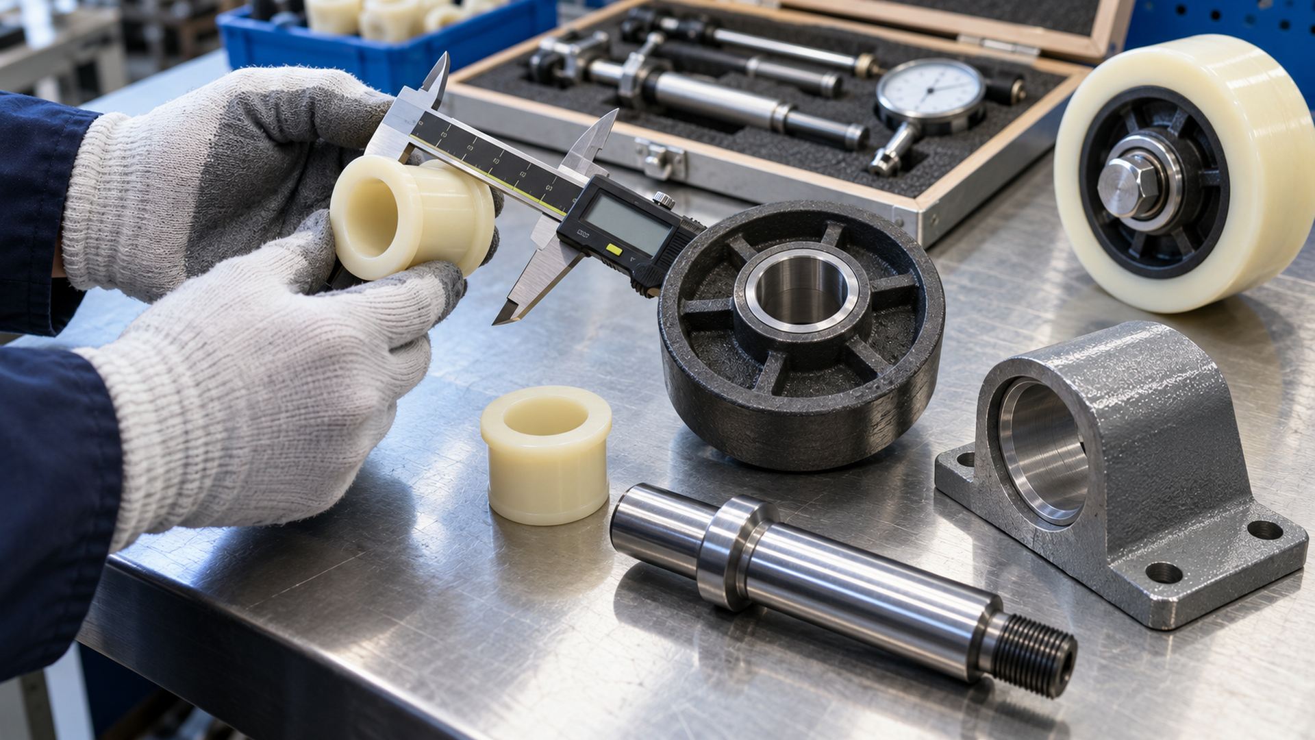 The bore, press-fit outside diameter, sleeve length, flange diameter and flange thickness all affect the final roller stack.
Common dimensions include:
| Dimension | Function in the roller | Common design risk |
|---|---|---|
| Bushing bore | Sliding fit with shaft | Too tight after press fitting or thermal change |
| Sleeve outside diameter | Retention in roller hub | Creep, hub cracking or insufficient interference |
| Sleeve length | Radial projected area and support | Edge loading if too short or housing misaligned |
| Flange outside diameter | Axial contact area and retention | Interference with bracket, recess or wheel face |
| Flange thickness | Axial stack and wear allowance | Clamping or side rubbing if stack is too tight |
| Chamfer and lead-in | Assembly and shaft entry | Cutting the bushing or shaving hub material |
| Roller running diameter | Track contact and rotational speed | Confusing wheel OD with bushing OD |
The installed bore may differ from the free bushing bore. Press fitting a thin polymer or composite sleeve into the wheel can reduce its inside diameter. The supplier should specify the housing bore and shaft size that produce the intended running clearance after installation.
SKF's guide to composite dry sliding bearings discusses housing and shaft tolerances for its PTFE and POM composite bushings, including flanged forms. Those recommendations belong to the specified bearing family and should not be copied blindly to every injection-moulded polymer bushing.
How Does a Flanged Bushing Fit the Complete Roller System?
The bushing sits between the wheel and shaft, while the flange interacts with the wheel side, washer or bracket.
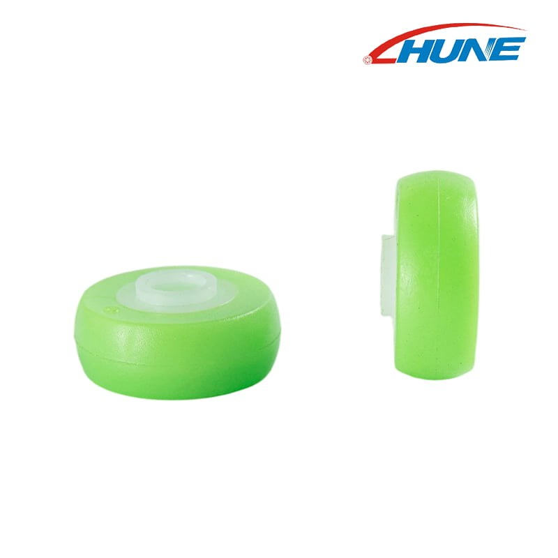 A bearing-free roller separates the track-contact material from the inner sliding interface; flange and axial geometry must still match the mounting system.
A typical load path is:
moving panel or machine element → bracket → shaft → bushing bore → bushing body → wheel → track
An axial disturbance may follow another path:
wheel side motion → bushing flange → washer, bracket or shaft shoulder → mounting structure
Both paths must remain aligned. A flexible bracket can tilt the shaft and concentrate radial load at one edge of the bushing. A rough washer can wear the flange. A bolt tightened against the rotating wheel can clamp the assembly and increase torque.
HUNE's light-duty plastic positioning roller uses a bearing-free dual-layer plastic construction with an inner smooth bushing interface. It illustrates why buyers should distinguish the outer running layer from the inner rotation interface. The exact flange form, shaft and side-clearance requirement should follow the project drawing.
Which Materials Are Used for Flanged Bushings?
Polymer, metal-polymer composite, sintered metal and solid metal bushings serve different speed, load, lubrication and environmental requirements.
Self-lubricating polymer
Engineered polymers can run dry, reduce weight, resist corrosion and damp vibration. Filled grades may improve wear or strength. Temperature, moisture, chemicals, creep, thermal expansion and shaft finish must be checked for the named grade.
Metal-polymer composite
A metal backing supports a low-friction sliding layer. These bushings can provide a thin wall and controlled bearing surface. Edge condition, installation damage, corrosion and the correct mating shaft remain important.
Sintered bronze or iron
Porous sintered bushings can retain lubricant and support established plain-bearing applications. Lubricant, storage, contamination and operating temperature need control. ISO 2795 provides standardized dimensions for certain sintered bearing forms, but the application rating still comes from the manufacturer.
Solid bronze or other metal
Machined metal bushings provide stiffness and temperature capability but may require lubrication, grooves or a hardened counterface. Direct metal-on-metal contact can raise noise and seizure risk if the lubrication regime is wrong.
igus describes its polymer flanged sleeve bearing as using the sleeve for radial load and the flange as an integrated thrust surface. This is useful functional guidance, but the permitted values remain material- and size-specific.
How Do Shaft Finish and Alignment Affect Wear?
The shaft is one half of the bearing pair, so its material, hardness, roughness and alignment can determine service life.
A shaft that is too rough can abrade a polymer or composite liner. A mirror-like finish is not automatically ideal for every self-lubricating material because transfer-film behavior can depend on the surface. Corrosion, plating defects and sharp shaft entry edges can also damage the bore.
The shaft should enter through a lead-in that does not shave the bushing. Its shoulder radius must clear the flange and allow full face contact where intended. If two bushings support one roller, their bores must remain coaxial after assembly.
Misalignment can create:
- edge loading in the sleeve;
- uneven flange contact;
- high starting torque;
- tapered wear;
- heat and squeal; and
- wheel runout at the track.
The shaft and bushing should therefore be reviewed together rather than purchasing the bushing by nominal bore alone.
How Should the Bushing Be Retained in the Roller?
The sleeve normally needs a controlled press fit or moulded retention, while the flange provides one-sided location.
For a separately moulded roller, the bushing may be pressed into a prepared hub. Housing diameter, roundness, chamfer, wall thickness and material condition affect the result. Excessive interference can close the bushing bore, distort the flange or crack the wheel hub. Insufficient retention can allow the bushing to rotate or move in the wheel.
The assembly tool should support the correct surface. Pressing through an unsupported thin flange can bend it. Applying force through the bore with a sharp tool can score the sliding surface. The bushing should enter squarely and seat fully without leaving mould flash or chips under the flange.
An overmoulded or two-material wheel can integrate the sliding layer during moulding. That route removes one assembly step but adds process-control questions around shrinkage, material bonding and bore condition. HUNE's roller materials and manufacturing guide explains how moulding and post-moulding assembly affect bearing retention.
Does a Roller Need One Flange or Two?
One flange locates one side; two-sided control needs another defined axial feature.
Common arrangements include:
- One flanged bushing plus shaft shoulder: The flange references one wheel face while the shoulder or washer controls the other side.
- Two flanged bushings inserted from opposite sides: Each flange provides a side face, while the sleeve lengths must not create an uncontrolled overlap or gap.
- Clip-in double-flange bushing: A flexible feature captures the housing from both sides after insertion.
- Straight bushing plus thrust washers: Radial and axial sliding surfaces are separate components.
- Single flanged bushing with free opposite side: Used when only one-sided retention is necessary and axial float is acceptable.
The correct arrangement depends on assembly access, bracket width, permitted float, thrust direction, replaceability and production volume. Avoid removing all axial clearance unless the material and thermal stack have been evaluated.
When Is a Ball Bearing Better Than a Flanged Bushing?
A rolling-element bearing is often better for higher speed, low running torque, controlled bearing life or heavier continuous duty.
A flanged bushing is a sliding bearing. Its friction and wear depend on pressure, speed, temperature, shaft condition and lubrication regime. A ball bearing separates the rotating rings with rolling elements and may provide lower running friction, particularly at higher speed.
Choose the architecture from the system requirement:
| Requirement | Flanged bushing may suit | Ball bearing may suit |
|---|---|---|
| Low speed and oscillation | Yes | Sometimes unnecessary |
| Dry, dusty light duty | Often, with suitable polymer | Possible with suitable sealing |
| Compact one-piece axial face | Strong advantage | Requires bearing shoulders or washers |
| Higher continuous speed | Requires careful p×v and heat review | Often preferred |
| Very low starting torque | Material-dependent | Often preferred |
| Continuous significant axial load | Only with rated flange design | Use a bearing arrangement rated for combined load |
| Predictable catalogue fatigue life | Not usually expressed like rolling-bearing L10 | Standard bearing calculations may apply |
Cost should include the shaft, washers, lubrication, assembly and replacement—not only the unit price of the bushing or bearing.
What Failure Modes Should an OEM Watch For?
Wear location usually reveals which interface or load was not controlled.
Common observations include:
- bore polishing or wear from radial sliding;
- one-sided bore wear from shaft misalignment;
- flange thinning from continuous thrust rubbing;
- melted or smeared polymer from excess heat;
- bushing rotation in the hub from inadequate retention;
- closed bore and high torque from excessive press fit;
- cracked hub from insufficient plastic wall;
- broken flange from assembly force or impact; and
- wheel-side rubbing caused by an incorrect axial stack.
Do not replace a failed flanged bushing with a harder grade before identifying the mechanism. A harder material can transfer wear to the shaft or bracket and leave the original alignment problem unchanged.
How Should an OEM Validate a Bushed Roller?
Inspect the installed dimensions, then test radial and axial behavior in the real bracket and track.
I use this sequence:
- confirm bushing material, free dimensions and supplier data;
- inspect roller hub size, roundness, chamfer and plastic condition;
- measure installed bore and flange seating after assembly;
- verify shaft size, finish, hardness and shoulder clearance;
- check rotational torque and axial float in the bracket;
- apply representative radial load and any expected side load;
- run at the intended speed, duty and temperature;
- inspect bore wear, flange wear, heat, debris and hub retention; and
- approve production gauges and sampling for critical dimensions.
A hand-spun sample proves only that the parts move at that moment. It does not establish wear life, thermal clearance or flange durability.
What Should a Buyer Send in a Flanged-Bushing Roller RFQ?
Send the bushing, roller, shaft and bracket geometry together.
Include:
- application and roller function;
- drawing, 3D model or physical sample;
- roller outside diameter, width and running profile;
- bushing bore, OD, sleeve length, flange diameter and thickness;
- preferred bushing material or performance requirement;
- shaft diameter, material, hardness, finish and shoulder geometry;
- hub material, wall thickness and assembly method;
- bracket width, washers and permitted axial float;
- radial load, axial load and load direction;
- speed, oscillation angle, travel and duty cycle;
- lubrication or dry-running requirement;
- temperature, moisture, dust and chemicals;
- expected service life and allowable wear;
- critical dimensions and inspection method; and
- sample quantity and annual volume.
If replacing an existing roller, include photographs of both side faces and the worn bore or flange. Wear evidence often clarifies whether the problem is radial, axial, thermal or related to retention.
Discuss a Bushed Roller with HUNE
HUNE can review the plastic wheel, bushing, shaft, bracket and track as one OEM assembly.
We manufacture injection-moulded roller components and coordinate bearings, shafts, studs, spacers, stamped brackets and related hardware. A project can begin from an existing sample, a complete drawing or an application requirement. We can compare a bearing-free bushing design with a ball-bearing roller when the duty is not yet fixed.
The HUNE rubber and plastic roller component range includes lightweight roller and positioning-wheel architectures that can be developed around approved geometry and materials. The OEM development process covers drawing review, tooling, moulding, hardware production, assembly and inspection.
Send the roller drawing, bushing and shaft dimensions, mating track, load, speed, environment and expected quantity through the HUNE contact page. These details allow a useful engineering and sourcing review before tooling or volume production.
Frequently Asked Questions
Is a flanged bushing the same as a flange bearing?
Not always. “Flange bearing” can describe a mounted ball-bearing unit with a bolt-on housing, while a flanged bushing is usually a plain sleeve bearing with an integral rim. Confirm the component drawing rather than relying on the name.
Can the flange carry axial load?
It can provide an axial sliding face when the specific bushing material and geometry are rated for it. The allowable load depends on contact area, pressure, sliding speed, temperature, lubrication and the mating face. A locating flange should not automatically be treated as a continuous-duty thrust bearing.
Does the flange stop a bushing from rotating in the wheel?
The flange stops movement through the housing in one direction, but it does not necessarily prevent circumferential rotation. Retention against rotation normally comes from the specified press fit, moulded feature or mechanical design.
Can a polymer flanged bushing run without grease?
Many self-lubricating polymer grades are designed for dry running, but not every polymer bushing is oil-free. Use the named material supplier's guidance and check shaft finish, pressure, speed, temperature and contamination.
Should a roller use two flanged bushings?
Two opposing flanges can control both side faces and increase radial support length, but the sleeve lengths and bracket stack must leave suitable clearance. One flanged bushing plus a washer or shoulder may be simpler. Select the arrangement from the load direction and assembly access.
Why does a flanged bushing become tight after installation?
Press fitting can reduce the bore, especially in thin polymer or composite bushings. An undersized housing, excessive interference, hub deformation, temperature or moisture can add further change. Specify housing and shaft dimensions for the installed condition.
Final Engineering Recommendation
Use a flanged bushing when a low-speed roller needs a plain radial bearing plus a compact one-sided locating or thrust face. Confirm that the flange has a real function, then size the bore, sleeve, flange and housing from the actual radial and axial load paths.
Before production, measure the installed bore and axial stack, verify shaft finish and alignment, and run the roller under representative pressure, speed, side contact and environment. If the application requires high speed, very low torque or sustained thrust, compare the flanged bushing with a rolling-bearing or dedicated thrust-bearing arrangement before freezing the tooling.


