

Radial load acts perpendicular to a shaft’s axis. Axial load, also called thrust load, acts parallel to that axis. A roller carrying the weight of a moving panel usually places radial load on its bearing. A wheel rubbing a side flange, a helical gear pushing along its shaft or a misaligned cable can add axial load.
The difference is simple to draw but important to calculate. Bearing load ratings, internal geometry, fits, clearance and support arrangements respond differently to the two directions. Many real machines apply both at the same time, and an offset force can also create a tilting moment. I therefore do not select an OEM bearing roller from total force alone. I first define the shaft axis, resolve every force into radial and axial components, locate its point of application and then check the complete wheel–bearing–axle–bracket system.
What Are Radial and Axial Loads?
Radial load crosses the shaft axis; axial load follows it. The shaft axis, rather than gravity or the machine frame, is the reference.
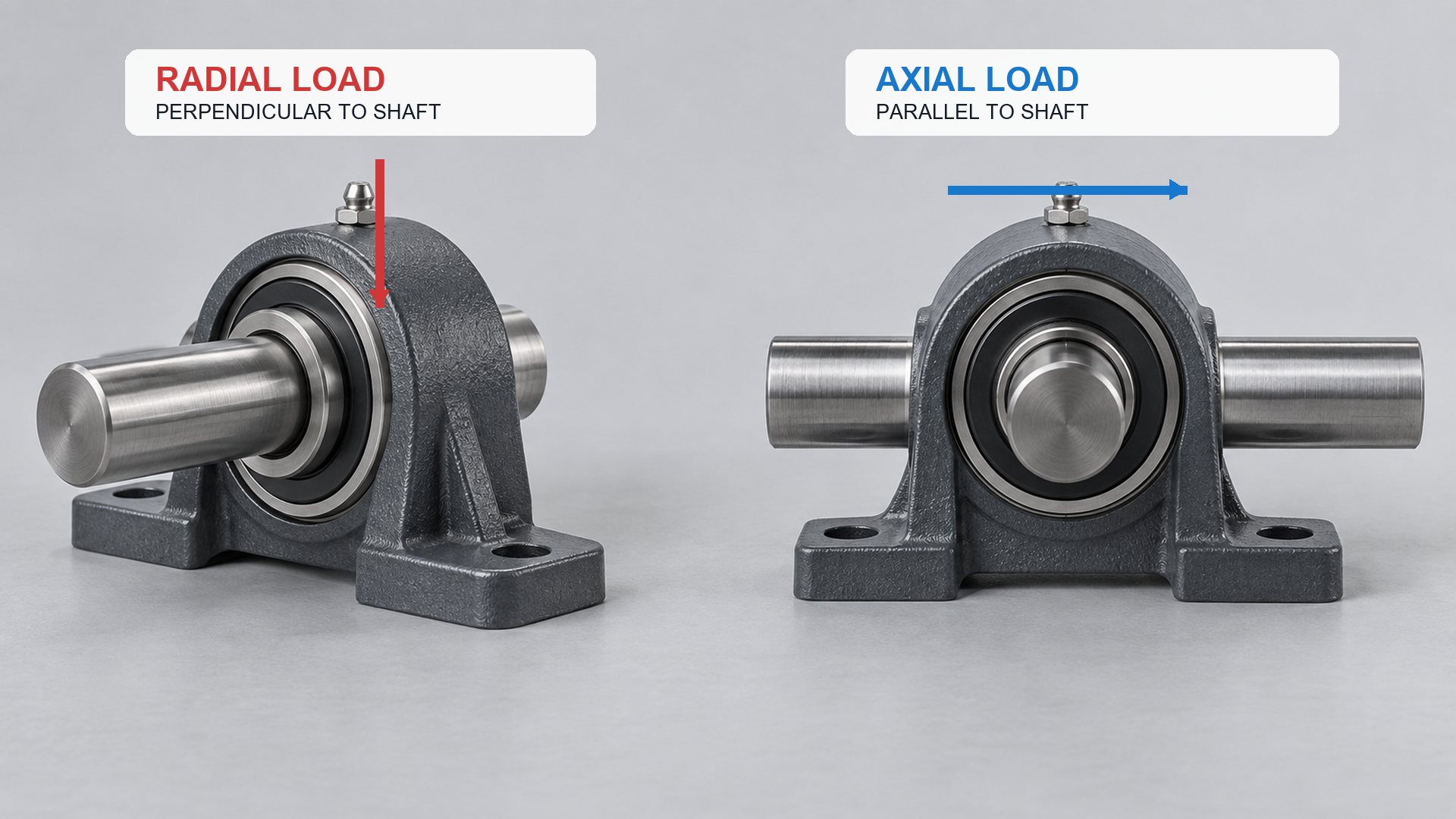
Imagine a horizontal roller axle running from left to right. A downward force on the wheel tread is perpendicular to that axle, so it is radial. A force pushing the wheel toward the left bracket plate is parallel to the axle, so it is axial.
Rotate the entire machine by 90 degrees and the names do not change. A vertical shaft can still receive radial load from the side and axial load from above or below. The terms always describe force relative to the bearing or shaft axis.
NSK’s deep-groove bearing technical page uses the same definition: loads perpendicular to the shaft are radial, while loads parallel to the shaft are axial or thrust loads.
Radial load
Radial load tends to push the inner and outer bearing rings sideways relative to each other. Common sources include:
- the weight carried by a door, drawer or machine carriage;
- contact force between a roller and track;
- belt or cable tension acting on a pulley;
- gear separation force;
- chain pull;
- spring force applied across a roller;
- acceleration of a supported moving mass.
Axial load
Axial load tends to move one bearing ring along the shaft axis relative to the other. Common sources include:
- helical gear thrust;
- lead-screw or ball-screw reaction;
- fan or propeller thrust;
- side contact between a grooved wheel and track;
- a roller rubbing a bracket or guide flange;
- misalignment that pulls a cable or belt out of the wheel plane;
- assembly preload or clamping transferred through the wrong ring.
Where Do These Loads Appear in Roller Systems?
The main track reaction is often radial, while axial load commonly enters through side guidance, misalignment or retention geometry.
| Roller-system condition | Main load direction | How it reaches the bearing | Engineering concern |
|---|---|---|---|
| Flat wheel carrying a panel on a level track | Radial | Tread → wheel → outer ring | Bearing rating, wheel compression and axle bending |
| Pulley redirecting a cable | Mostly radial | Cable tension resultant → groove → bearing | Wrap angle and cable tension determine direction and magnitude |
| Wheel continuously rubbing a track flange | Axial plus radial | Side face or groove flank → wheel → bearing | Heat, wear and unintended thrust |
| V-groove wheel on an angle track | Combined | Two inclined contact normals resolve into components | Track angle, contact symmetry and bearing arrangement |
| Roller mounted on an offset stud | Radial plus moment | Contact force acts away from support | Stud bending and uneven bearing load distribution |
| Helical-gear-supported shaft | Radial plus axial | Gear mesh produces tangential, separating and thrust forces | Bearing type and locating arrangement |
| Two rollers guiding both sides of a rail | Radial on each wheel, possible preload | Opposing contacts locate the moving part | Assembly spacing and thermal growth |
A component can change load direction without changing its total force. For example, a groove flank redirects a portion of the track reaction along the axle. This is why a buyer should provide the track or cable geometry rather than only the nominal load.
How Is an Angled Force Split into Radial and Axial Components?
Resolve the applied force relative to the shaft axis before using a bearing catalogue.
If a force F acts at an angle θ measured from the shaft axis:
Axial component: Fa = F × cos θ
Radial component: Fr = F × sin θ
With this definition:
- at θ = 0°, the force is entirely axial;
- at θ = 90°, the force is entirely radial;
- between those limits, the bearing receives combined loading.
The equation only resolves one known force. A real roller may have several forces from gravity, track contact, springs, acceleration and side guidance. Their components must be added as vectors in the correct coordinate directions. Opposing forces can partly cancel; forces acting at different positions can create a moment even when their net force appears small.
I also separate operating conditions. Normal travel, start-up, braking, impact, track joints and end stops may produce different force directions and peaks. A single average load can hide the condition that controls the axle, bracket or bearing.
What Is a Combined Bearing Load?
Combined load means radial and axial forces act on the bearing at the same time; it is not evaluated by simply adding the two numbers.
Bearing manufacturers convert an actual combined condition into an equivalent load using factors that depend on bearing type, geometry and the ratio of axial to radial load. A common form for a radial bearing is:
P = XFr + YFa
Where:
- P is the dynamic equivalent radial load;
- Fr is the actual radial load;
- Fa is the actual axial load;
- X and Y are manufacturer-specified load factors.
The factors are not universal constants. They can change with bearing type, contact angle, internal clearance and the ratio Fa/Fr. NTN’s rolling-bearing handbook explains dynamic equivalent load and provides the same general expression for radial bearings.
ISO 281:2007 specifies methods for rolling-bearing dynamic load ratings and rating life. Its scope and assumptions matter: calculated rating life is a fatigue calculation under defined conditions, and the standard does not cover every failure mechanism such as wear, corrosion or electrical erosion.
For an OEM decision, equivalent load is one input. The design must still satisfy static safety, speed, lubrication, contamination, alignment, stiffness, temperature and required reliability.
Which Bearing Types Carry Radial or Axial Load?
Bearing geometry determines the useful balance between radial and axial capacity. No bearing should be selected from its outside dimensions alone.
| Bearing type | Radial-load capability | Axial-load capability | Typical design implication |
|---|---|---|---|
| Deep-groove ball bearing | Good for many compact applications | Can accept limited axial load in both directions | Common in small bearing rollers; verify the actual combined-load limit |
| Angular-contact ball bearing | Carries radial load | Designed for significant axial load in one direction per single row | Often paired when axial location is required in both directions |
| Double-row angular-contact bearing | Higher radial support than a similar single row | Axial load in both directions | Wider package with greater moment support |
| Tapered roller bearing | High radial capacity | Carries axial load in one direction and develops internal thrust | Normally used in opposed pairs or a defined locating arrangement |
| Cylindrical roller bearing | High radial capacity | Limited or design-dependent axial guidance | Useful where radial load and stiffness dominate |
| Thrust ball or roller bearing | Not intended as a general radial support | Designed mainly for axial load | Usually combined with separate radial guidance |
| Self-aligning ball or spherical roller bearing | Radial load with misalignment capability | Some designs accept combined load | Larger system and different friction or speed characteristics |
A deep-groove ball bearing is common inside plastic or polyurethane rollers because it is compact and handles radial load efficiently while accepting some axial load. “Some” is not a purchasing value. The permissible axial component depends on bearing size, internal design, clearance, speed, fit and lubricant.
HUNE’s guide to how bearings reduce friction explains the rolling and sliding contacts inside common bearing types. The bearing-clearance guide shows why a press fit or temperature change can alter the installed condition used in a load calculation.
How Can a Grooved Roller Create Axial Load?
A centered groove can guide a track without continuous side thrust, but asymmetric flank contact converts part of the reaction into axial load.
A U-groove, V-groove or round-groove wheel is not loaded only by the weight it carries. The normal force at each contact surface acts perpendicular to that surface. Inclined groove flanks therefore produce components that can act both radially and axially relative to the wheel axle.
When contact is symmetric on both sides of a groove, opposing axial components may balance at the wheel level. Manufacturing variation, track position, bracket deflection or side acceleration can shift the contact to one flank. The remaining axial component then passes through the wheel hub and bearing into the axle and bracket.
Continuous flange rubbing should not be treated as a normal bearing duty unless the system is designed for it. It can indicate:
- the groove does not match the track profile;
- the two rails are not parallel;
- the bracket is twisted;
- the wheel spacing is incorrect;
- the track has dimensional variation;
- the moving panel applies a side moment;
- the axle or housing lacks stiffness.
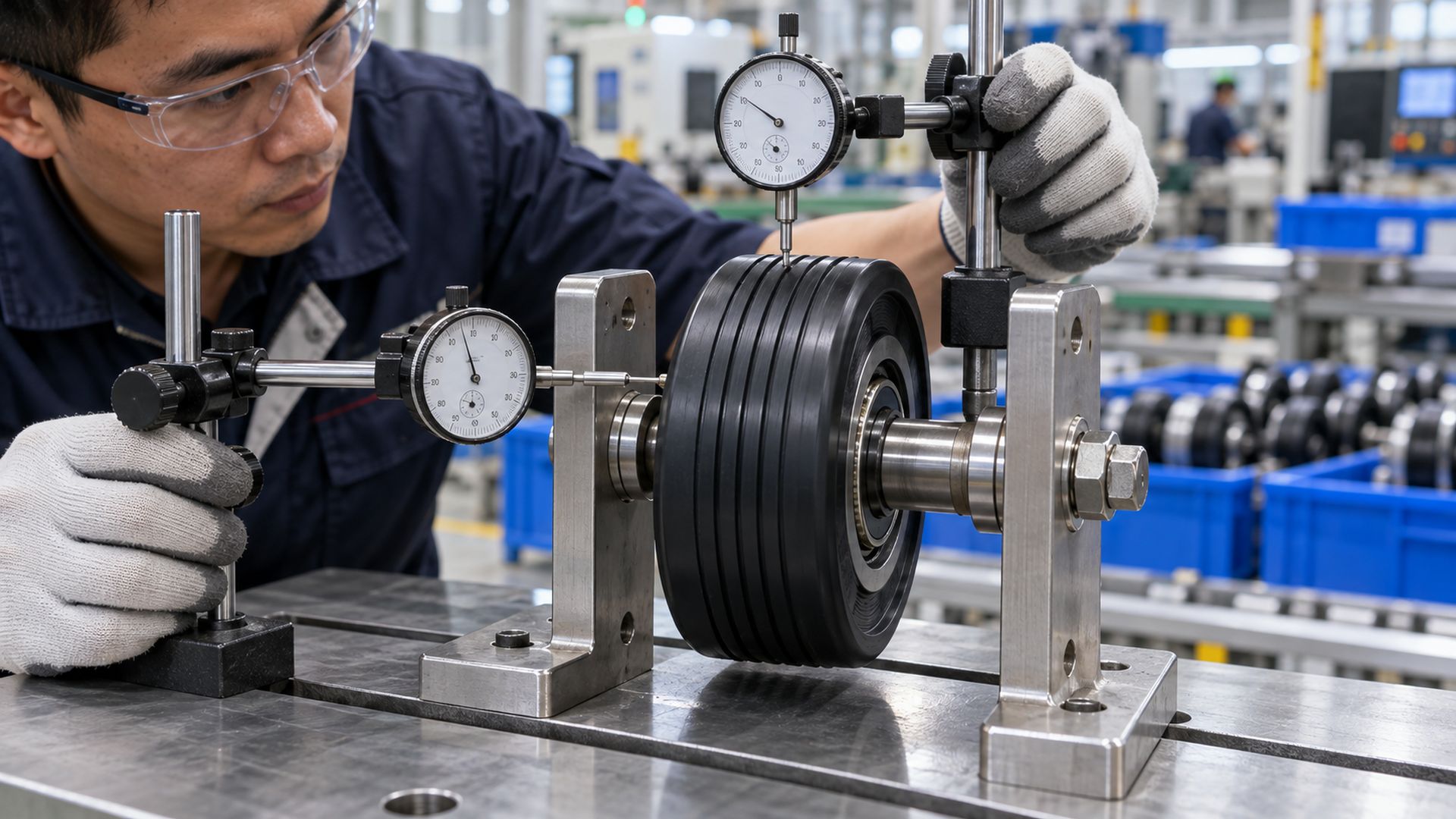
HUNE’s U-groove bearing pulley wheels combine a moulded running profile with an internal bearing. The published wheel dimensions help define fit and packaging, but the equipment drawing must still define track geometry and load direction.
What Is a Moment Load?
A moment load is the turning effect created when a force acts at a distance from the support; it can load two bearings very differently.
Moment is force multiplied by perpendicular distance:
M = F × e
Where e is the offset between the force line and the relevant support or bearing centre. A roller on a long cantilevered stud can therefore produce a large bending moment even when its radial force is moderate.
Moment load is not simply another arrow parallel or perpendicular to the shaft. It describes the tendency to rotate or tilt the assembly. The reaction appears as different forces at the bearings, shaft shoulders, bracket plates or mounting bolts.
Two bearings spaced apart can resist a tilting moment more effectively than one narrow bearing, but only if the seats, shaft and bracket distribute the load. HUNE’s comparison of single-bearing and double-bearing rollers explains why adding a second bearing does not automatically double capacity.
How Do Axle, Spacer and Bracket Geometry Affect Load Direction?
A suitable bearing can still fail or bind if the mounting converts alignment error or fastener force into unintended axial load.
I normally inspect these interfaces:
- Axle shoulder. It should support the intended inner-ring face without contacting the seal or rotating wheel.
- Spacer length. A short spacer can allow the bracket to squeeze inward when the bolt is tightened.
- Bracket parallelism. Non-parallel plates can tilt the axle and introduce combined or edge loading.
- Bearing-seat fit. An excessive wheel interference fit can reduce internal clearance and raise torque.
- Axial retention. Snap rings, shoulders or washers should locate the intended ring without transmitting clamping through the rolling elements.
- Cantilever distance. Increasing the distance from track contact to bracket support increases bending moment.
- Wheel side clearance. Too little clearance creates rubbing; too much clearance may permit unstable guidance.
- Fastener stiffness. Bolt stretch, axle bending and bracket deformation change the actual load distribution.
Functional dimensions belong on the assembly drawing. Bearing bore and outside diameter alone do not control how the installed roller reacts to radial, axial and moment loads.
What Do Dynamic and Static Load Ratings Mean?
Dynamic rating supports fatigue-life calculation; static rating addresses permanent deformation risk. Neither is a direct maximum machine load.
For radial bearings, catalogues commonly list basic dynamic radial load rating C and basic static radial load rating C0. These values are defined under standardized bearing conditions. They do not mean that the bearing may carry the same axial load, and they do not include the strength of the wheel, axle or bracket.
Dynamic analysis uses equivalent load, speed and required life. Static analysis checks whether peak or stationary loading can create unacceptable permanent deformation at the most heavily loaded rolling contact. Shock, vibration and impact may require additional factors or application-specific evaluation.
The Timken Engineering Manual covers bearing reactions, equivalent radial and axial loads and minimum-load considerations. I use current data from the selected manufacturer because load factors, limits and calculation procedures depend on the specific bearing family.
How Should an OEM Validate the Installed Roller?
Calculate the load directions first, then verify the complete assembly under radial, axial and moment conditions representative of service.
A practical validation sequence is:
- Draw the shaft axis and force vectors for every operating condition.
- Resolve angled forces into radial and axial components.
- Locate each force and calculate relevant moments about the bearing supports.
- Determine reactions at each bearing rather than dividing total load equally without justification.
- Use the selected manufacturer’s equivalent-load factors and life method.
- Check static safety for peak, impact and stationary loads.
- Build the production-intent wheel, bearing, axle, spacer and bracket assembly.
- Apply representative radial load and measure torque, temperature, deflection and tracking.
- Apply the defined axial component or side-guidance condition and inspect rubbing or displacement.
- Run repeated duty cycles, including reversals, stops and worst-case alignment.
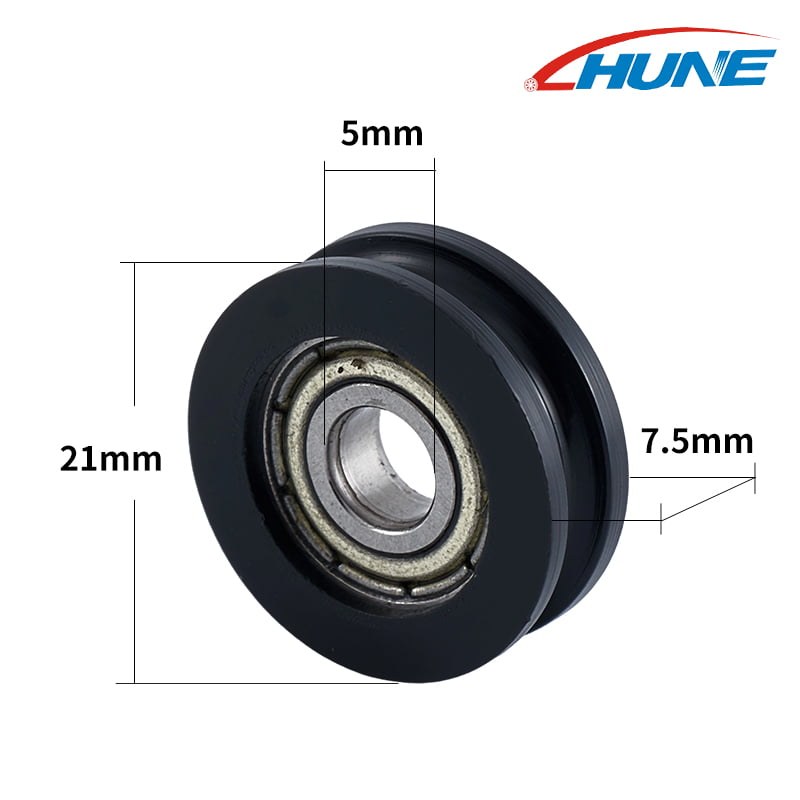
- Recheck radial runout, axial movement, noise, free rotation and component damage.
- Record the approved bearing designation, fits, clearances and assembly conditions on controlled drawings.
Radial runout and axial movement are useful assembly measurements, but they are not the same as applied radial and axial load. A dial indicator measures displacement; the test fixture must provide a known force if stiffness or compliance is being evaluated.
What Should a Buyer Send to the Supplier?
A useful bearing-roller inquiry defines force direction, point of application and mounting geometry.
Send the supplier:
- equipment function and roller position;
- assembly drawing showing the shaft axis and track, cable or belt contact;
- normal and maximum radial load;
- axial load magnitude and direction, including reversals;
- force location and cantilever distance;
- any shock, vibration, acceleration or end-stop condition;
- speed, duty cycle, required life and operating temperature;
- wheel outside diameter, running diameter, width and groove geometry;
- bearing bore, outside diameter, width and approved designation;
- axle, shoulder, spacer, washer and bracket dimensions;
- fit, internal-clearance, lubrication and sealing requirements;
- allowable torque, runout, axial movement, noise and deflection;
- validation method, sample quantity and forecast production volume.
If the loads are not yet calculated, provide the machine geometry and operating forces rather than a guessed bearing rating. HUNE’s OEM development process explains how requirements, drawings, samples and installed testing can be translated into a controlled production specification.
Discuss a Bearing Roller Load Case with HUNE
HUNE, Zhejiang Huaneng Micro Bearing Co., Ltd., manufactures deep-groove ball bearings, plastic-coated bearing rollers, injection-moulded wheels and customised roller assemblies. We can review the wheel, bearing, axle, spacers, bracket and mating track as one load path.
Send your assembly drawing, radial and axial forces, load locations, speed, duty cycle, validation plan and expected quantity through the HUNE contact page. This information helps determine whether an existing bearing roller is suitable or a different wheel, bearing arrangement or bracket structure should be developed.
Frequently Asked Questions
Is gravity always a radial load?
No. Gravity is radial only when it acts perpendicular to the bearing’s shaft axis. On a vertical shaft, gravity can create axial load. Always define the shaft axis before naming the load direction.
Can a deep-groove ball bearing carry axial load?
Yes, many deep-groove ball bearings can carry limited axial load in both directions. The permissible amount depends on the specific bearing, radial load, internal clearance, fit, speed, lubrication and manufacturer data.
Is thrust load the same as axial load?
Yes. In bearing terminology, thrust load commonly means a force acting parallel to the shaft axis.
Does a double-bearing roller eliminate axial load?
No. Two bearings can improve support and moment resistance, but external axial force still has to be reacted by the bearing arrangement, shoulders, spacers and bracket. Load sharing depends on geometry and stiffness.
Can radial and axial load ratings be added together?
No. Use the bearing manufacturer’s equivalent-load method and factors for the selected bearing type. The calculation normally depends on the ratio of axial to radial load and other bearing-specific values.
Practical Engineering Recommendation
Draw the shaft axis, force direction and force location before selecting the bearing. Resolve each operating force into radial and axial components, calculate any moment from offset loading, and determine the reactions at every support. Then check the chosen bearing with current manufacturer data and validate the complete wheel–bearing–axle–bracket assembly under representative combined loading.


