

Belt or cable tension affects pulley bearing life by creating forces on both sides of the pulley. Their vector resultant passes through the groove, wheel, bearing, axle and bracket. Higher tension generally raises the bearing's equivalent load, and calculated fatigue life falls rapidly because bearing life is related to load by a power law. The result also depends on direction-change angle, belt pretension, tight-side and slack-side forces, speed, shock and how long each load level occurs.
I do not use one “working tension” as the complete bearing input. I calculate each span force and direction, determine the reactions at the bearing supports, build a representative load spectrum and check static peaks separately. The pulley bearing must then be validated inside the production-intent wheel, axle and bracket because alignment, groove contact and mounting can add loads that a tension value alone does not show.
How Does Tension Become Pulley Bearing Load?
A pulley bearing reacts the vector combination of the entering and leaving span forces, not one tension value in isolation.
The basic load path is:
Belt or cable span forces → groove or tread → wheel and hub → bearing outer ring → rolling elements → inner ring → axle → bracket
For a direction-changing cable with equal tension T on both sides, define δ as the change in travel direction. Ignoring friction and other loads, the resultant at the pulley center is:
R = 2T × sin(δ / 2)
At zero direction change, the cable continues straight and the ideal redirection resultant is zero. At a 180° reversal, the two tension forces act in the same resultant direction and R = 2T. If a drawing instead defines the included angle between the free spans, the equation may use a cosine form. The angle definition must be shown.
When the two tensions differ, use vector addition. With the same direction-change definition:
R = √(T1² + T2² − 2T1T2 cos δ)
The resultant is then resolved through the shaft and bearing arrangement. A pulley with two bearings does not necessarily divide the load equally; support spacing, fit, stiffness, alignment and force position determine each reaction.
The Timken Engineering Manual treats belt forces as applied loads that must be converted into bearing reactions before life selection. HUNE's broader pulley-bearing engineering guide explains how the bearing, wheel, axle, retention and bracket form the complete support system.
How Do Tight-Side, Slack-Side and Pretension Forces Differ?
A drive belt normally loads the pulley through both spans; transmitted torque comes from their tension difference, while bearing reaction depends on their vector combination.
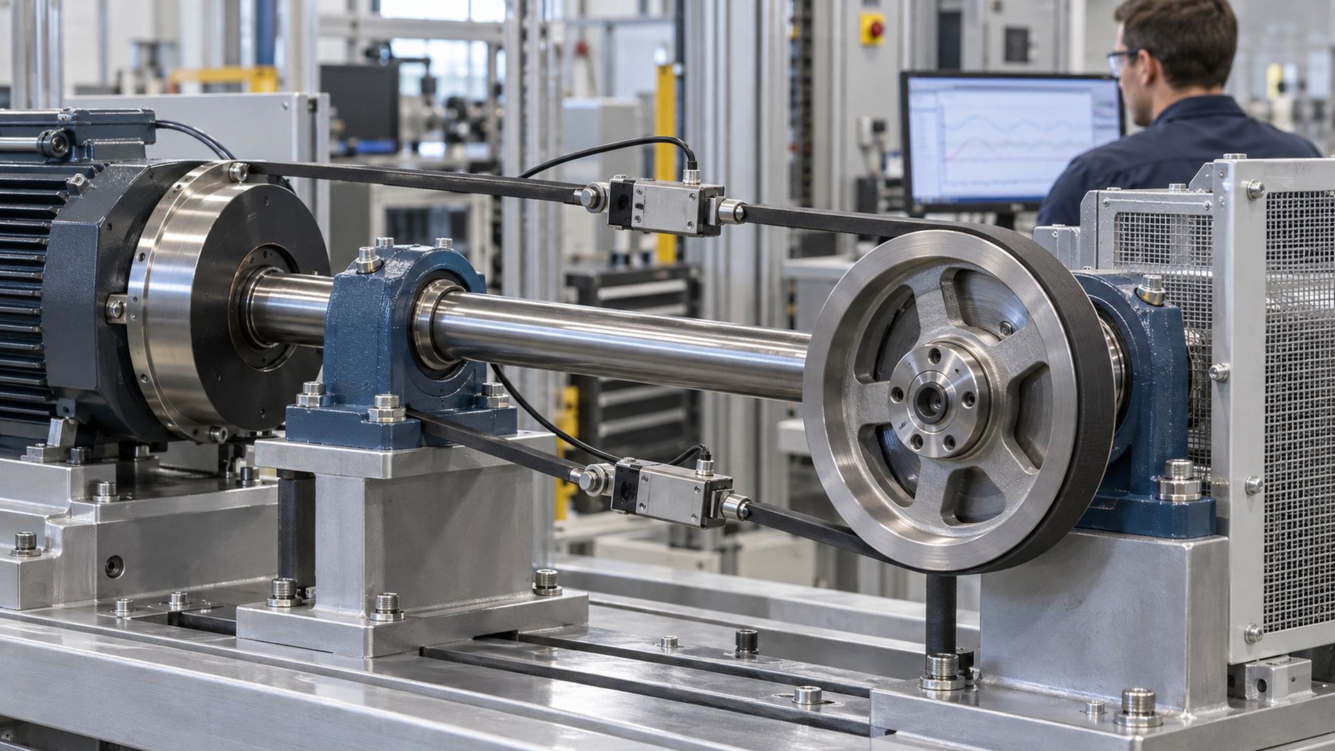
In a simplified belt drive:
M = (T1 − T2) × re
Where M is transmitted torque and re is effective pulley radius. The tight-side tension T1 exceeds the slack-side tension T2 while transmitting torque. The difference produces torque, but both span forces act on the pulley and shaft.
Pretension establishes a baseline force before useful torque is transmitted. It helps maintain traction and stable engagement, but it also loads bearings whenever the belt remains tensioned. A machine can therefore have low transmitted torque and still impose significant bearing load if pretension is high.
| Tension component | Why it exists | Bearing-life implication |
|---|---|---|
| Installation pretension | Establishes belt engagement and traction | Creates continuous baseline bearing load |
| Tight-side tension | Transmits torque under load | Raises resultant during powered operation |
| Slack-side tension | Maintains return-span control and engagement | Still contributes to shaft and bearing reaction |
| Tensioner force | Controls belt path or compensates for stretch | Adds another pulley load and can vary with travel |
| Cable working tension | Transmits pulling force or supports a moving load | Combines with direction change at each pulley |
| Acceleration peak | Changes moving-system force during starts and stops | May dominate short load blocks or static checks |
| Shock or jam load | Results from impact, snagging or abrupt stop | Requires separate peak and damage assessment |
The Gates Heavy Duty V-Belt Drive Design Manual uses defined drive geometry and belt ratings rather than treating belt tension as a single universal number. The applicable belt supplier's installation and design method should control the tension range.
Why Does Higher Tension Reduce Calculated Bearing Life So Quickly?
Bearing rating life has a power relationship with equivalent load, so life is highly sensitive to the load produced by tension.
For bearings whose dynamic rating is based on one million revolutions, a common basic equation is:
L10 = (C / P)^p million revolutions
Where:
- C is the bearing's basic dynamic load rating;
- P is the dynamic equivalent bearing load;
- p is normally 3 for ball bearings and 10/3 for roller bearings in this equation form.
ISO 281:2007 defines methods for dynamic load ratings and rating life. Its basic rating life is associated with 90% reliability under the standard's stated assumptions. It does not predict the exact life of one installed pulley and does not cover every failure mechanism such as wear, corrosion or electrical erosion.
Because P is raised to a power in the denominator, a tension increase that raises the equivalent bearing load can cause a much larger reduction in calculated fatigue life. This is why I avoid approving belt tension by feel or selecting a bearing from nominal payload alone.
The correct P may include radial and axial components. Belt skew, cable fleet angle, flange contact or a twisted bracket can add axial load even when the intended tension resultant is radial. The selected bearing manufacturer's equivalent-load factors must be used.
Why Is Average Tension Often the Wrong Life Input?
Short periods of high tension can consume life much faster than long periods of light load, so a simple arithmetic average can hide the controlling duty.
Many pulley systems operate through repeated stages:
- idle under pretension;
- acceleration;
- steady travel;
- deceleration;
- reversal;
- dwell under load;
- occasional overload, jam or end-stop event.
The load and speed during each stage should be represented. The SKF guide to bearing life and load ratings describes reducing variable operation into load blocks and combining the life fractions:
L10,total = 1 / (U1/L10,1 + U2/L10,2 + … + Un/L10,n)
Where Ui is the fraction of revolutions or duty assigned to each condition and L10,i is the calculated life for that condition. Representative load diagrams are essential because rare heavy loads can consume life much faster than light-load operation.
The Timken Engineering Manual also discusses weighted load and life for varying speed, load and time. It notes that extreme conditions still need separate contact-stress and alignment review. I prefer to calculate distinct operating blocks when speed also changes because lubrication and temperature may not follow a single averaged condition.
How Do Starts, Stops and Reversals Change Tension?
Dynamic tension can exceed steady-running tension when the system accelerates, brakes, reverses or takes up slack.
The peak depends on moving mass, acceleration, elasticity, damping, control profile and backlash or slack. A smooth speed command can produce a different tension history from an abrupt motor start even when the final speed and payload are identical.
Potential peak sources include:
- servo acceleration and emergency stopping;
- a cable becoming taut after slack travel;
- belt tooth engagement or splice passage;
- load oscillation and structural resonance;
- tensioner movement at travel limits;
- reversal in reciprocating equipment;
- intermittent product contact in packaging or conveying machinery;
- a cable snag, jam or pulley obstruction.
A short peak may contribute relatively few fatigue cycles but still create permanent indentation, ring movement, axle bending or bracket deformation. Dynamic life and peak-load checks solve different questions.
Does Stationary Tension Count Against Bearing Life?
Stationary tension does not accumulate rolling revolutions, but it can still create static contact stress and interact with vibration, corrosion and lubricant conditions.
A stopped machine can hold belt pretension or suspended cable load for long periods. The bearing contacts remain loaded at fixed positions. The designer should check static equivalent load and the applicable static safety factor, particularly when shocks or vibration occur while stationary.
ISO 76:2006 specifies methods for basic static load rating and static equivalent load. That check is separate from dynamic rating life. A bearing can satisfy a calculated L10 target yet be unsuitable for severe stationary shock or a high static load.
Transport vibration under tension can also mark contact surfaces without normal rotation. Moisture trapped during long dwell can make corrosion the controlling mechanism. These risks are not solved by increasing the calculated fatigue life alone.
Can Excessive Tension Affect Lubrication and Temperature?
Higher internal load can increase frictional heat and reduce the margin for poor lubrication, while tension also changes shaft and housing deflection.
Temperature is produced by the complete system: bearing friction, seal contact, grease churning, belt or cable friction, misalignment and surrounding heat sources. Excessive tension can raise bearing load and bend the shaft, changing load distribution across the rolling contacts.
Lubricant viscosity falls as temperature rises. The resulting film condition depends on bearing size, speed, load, lubricant and contamination. A bearing that runs acceptably at the same speed under light tension may behave differently under sustained high tension.
Closure selection also changes protection and torque. HUNE's guide to sealed and shielded bearings explains the protection-versus-friction trade-off. The correct closure still needs validation with the application's tension, speed and environment.
Is Lower Tension Always Better?
No. Tension must be high enough for stable traction, engagement and cable control; insufficient tension can create slip, impact and unstable loading.
Under-tensioned belts can slip, vibrate, whip or lose tooth engagement, depending on the drive type. A loose cable can leave the groove, strike a flange or create impact when it becomes taut. These conditions may reduce steady bearing load yet increase shock, heat or wear elsewhere.
The correct target is an approved operating range, not the lowest possible number. That range should come from:
- transmitted torque or working force;
- belt or cable supplier requirements;
- span length and stiffness;
- drive and tensioner geometry;
- environmental and temperature changes;
- manufacturing and assembly variation;
- the allowable loads of bearings, shafts, brackets and flexible members.
Tension should also be measured by a defined method. A static installation value, frequency-based span measurement and inline operating load are different measurements and should not be mixed without a correlation method.
How Do Alignment and Mounting Amplify Tension Load?
Misalignment can turn a calculated radial resultant into combined radial, axial and moment loading.
The same nominal tension can be more damaging when:
- the pulley is cantilevered far from the support;
- the shaft bends under tension;
- two bracket plates are not parallel;
- the belt or cable enters outside the pulley plane;
- the groove centerline is offset from the bearing reaction plane;
- the bearing seat is tilted or distorted;
- spacers transmit clamp force through the wrong bearing ring;
- groove or tread runout creates cyclic load.
If the resultant R acts at perpendicular offset e from the support plane, the resulting moment is M = R × e. A modest tension force can therefore create significant bearing misalignment when the cantilever distance is long.
I normally request the bracket and axle drawing with the pulley drawing. A bearing number and wheel outside diameter do not show the support conditions that determine installed life.
How Does the Complete Pulley Assembly Change Bearing Life?
The bearing is only one link; the wheel, hub, axle, spacers, bracket and flexible member can either preserve or distort the intended load path.
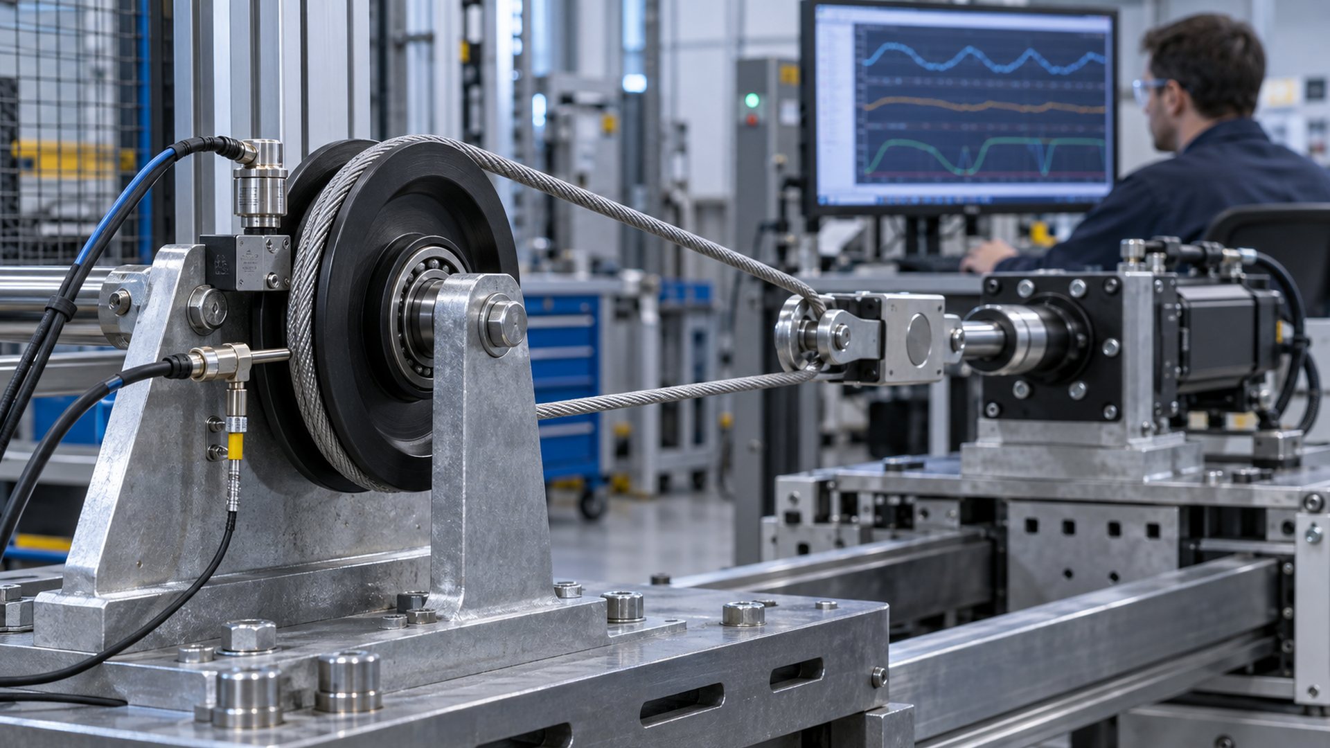
A plastic-coated or moulded bearing pulley must retain the bearing without reducing its operating clearance excessively. The wheel should carry groove contact into the outer ring without cracking, creeping or losing concentricity. The axle and bracket must maintain alignment under the same tension used in the life calculation.
Failure may begin outside the bearing:
| Assembly element | Tension-related risk | Useful validation |
|---|---|---|
| Groove or tread | Wear, heat, slip or flange contact | Contact pattern and profile inspection |
| Wheel hub | Creep, cracking or bearing-seat relaxation | Fit and runout before and after duty test |
| Bearing | Fatigue, heat, lubricant distress or seal damage | Torque, temperature, vibration and teardown |
| Axle or stud | Bending, fretting or shoulder damage | Deflection and contact inspection |
| Spacer and retention | Unintended axial preload | Free-running torque after assembly |
| Bracket | Twist or loss of alignment | Loaded geometry over full travel |
| Belt or cable | Edge wear, broken wires, coating damage or stretch | Supplier-defined inspection and elongation checks |
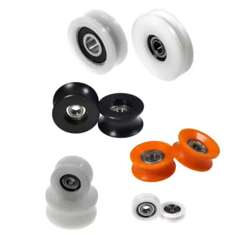
HUNE's U-groove bearing pulley wheels show several bearing-integrated constructions for cable, cord and round-track guidance. The sliding rollers with bearing range provides other wheel and mounting references. Published dimensions remain a starting point; application load and validation control approval.
The comparison of a bearing pulley and plain-bore pulley is also relevant when speed, friction, cost and maintenance route are still open design decisions.
How Should an OEM Validate Tension and Bearing Life?
Measure or calculate the real tension history, then reproduce the critical load blocks on a production-intent pulley assembly.
 A practical validation sequence is:
- Define end of life. State whether the limit is fatigue, noise, torque, temperature, runout, groove wear, belt or cable damage, or another equipment requirement.
- Map the force path. Record both span directions, direction-change angle, tensioner forces and support locations.
- Build the load spectrum. Separate installation pretension, acceleration, steady operation, deceleration, reversal, dwell and credible peaks.
- Calculate reactions. Resolve radial, axial and moment loads at each bearing.
- Check dynamic and static conditions. Use manufacturer data for life and a separate static assessment for peaks and dwell.
- Confirm the installed bearing condition. Verify fits, clearance, alignment, retention and rotating torque.
- Test the complete assembly. Use production-intent wheel material, bearing, lubricant, seals, axle, spacers and bracket.
- Monitor useful indicators. Depending on the application, record tension, speed, bearing temperature, torque, vibration, noise and tracking.
- Inspect after testing. Review raceways, grease, seals, groove wear, fit movement, axle fretting and bracket deformation.
- Control repeat production. Freeze the approved belt or cable specification, tension range, bearing designation, wheel geometry, assembly process and inspection method.
Increasing tension simply to shorten an endurance test can create a different failure mode. An accelerated test should preserve the relationship among load, speed, lubrication, temperature and alignment that controls the real application.
What Should a Buyer Send to the Supplier?
A useful pulley-bearing inquiry includes the tension range and duty cycle, not only the maximum tension.
Send:
- equipment function and pulley position;
- belt, cable or rope specification and supplier;
- span directions and direction-change angle;
- installation pretension and measurement method;
- tight-side and slack-side tension for drive pulleys;
- normal, peak and emergency tension;
- speed, starts, stops, reversals and time at each operating condition;
- transmitted torque or power where applicable;
- pulley effective diameter, groove profile and wheel width;
- bearing designation, closure and lubricant requirement if controlled;
- axle, shoulder, spacer, retention and bracket drawing;
- bearing support spacing and cantilever distance;
- environment, temperature, dust, moisture and chemicals;
- required life and the precise end-of-life criterion;
- acceptable noise, torque, runout, temperature or wear;
- validation method, sample quantity and forecast production volume.
For custom parts, HUNE's material and process overview explains how bearing selection, wheel material, moulding or coating and final assembly can be coordinated around one controlled specification.
Discuss a Pulley Bearing Life Requirement with HUNE
HUNE manufactures deep-groove ball bearings, plastic- and rubber-coated bearing rollers, U-groove pulley wheels and related OEM hardware. We can review span tension, wheel geometry, bearing, axle, spacers and bracket as one installed load path.
Send the assembly drawing, belt or cable specification, span directions, tension spectrum, speed, environment, required life endpoint and expected quantity through the HUNE contact page. These inputs allow an existing pulley structure and a custom design to be compared against the same operating requirement.
Frequently Asked Questions
Does doubling cable tension double the pulley bearing load?
If both span tensions double while their directions remain unchanged, the ideal vector resultant also doubles. The actual reactions can still include wheel weight, acceleration, side force and moment from an offset pulley. Bearing life does not then simply halve because rating life has a power relationship with equivalent load.
Is maximum tension the correct value for an L10 life calculation?
Not always. Maximum tension must be checked for static or peak damage, but using it continuously may misrepresent a variable-duty application. Build representative load and speed blocks, calculate life for each condition with the bearing manufacturer's method and combine the life fractions. Do not omit rare heavy events from the load history.
Does belt pretension affect bearing life when no torque is transmitted?
Yes. Pretension applies span forces to the pulley and bearings even at zero useful torque. It may be necessary for traction or engagement, but unnecessary excess increases baseline bearing load. The target range should follow the belt-system design and be verified with a defined installation method.
Can low cable tension improve pulley bearing life?
Lower controlled tension generally reduces calculated bearing load, but tension that is too low can allow slip, whip, groove exit or impact when slack is taken up. The correct tension must satisfy cable control and drive requirements as well as bearing life.
Does a larger pulley cancel the effect of high tension?
No. If span tension and direction change remain the same, static resultant force at the axle remains the same even when pulley diameter changes. A larger pulley changes bearing speed, flexible-member bending and torque relationships, which may influence the final design indirectly.
Practical Engineering Recommendation
Treat tension as a time-dependent load input, not a single catalogue value. Define both span forces and directions, calculate the bearing reactions for each duty block, check static peaks separately, and then validate the production-intent wheel–bearing–axle–bracket assembly. For sourcing, send the supplier the tension measurement method and complete load spectrum so bearing selection and pulley testing are based on the same operating conditions.



[…] The direction and magnitude of the load matter more than the bearing name by itself. Our article on how belt or cable tension affects pulley bearing life explains why tension affects the bearing and support structure […]