

Bearing life is determined first by the relationship between the bearing's dynamic load rating and its actual equivalent load. Speed converts a life stated in revolutions into operating hours. Required reliability, bearing type and size also affect the calculated result. Actual service life then depends on lubrication, contamination, temperature, fits, internal clearance, alignment, shock, vibration, electrical current, handling and the stiffness of the surrounding assembly.
For a bearing inside a plastic or metal roller, I do not treat catalogue life as the life of the complete roller. The wheel, bearing seat, axle, spacers, bracket and mating track can change the load and the bearing's installed clearance. The practical answer to “what determines bearing life?” is therefore a calculation plus an installed-system validation, not a catalogue number alone.
What Does Bearing Life Mean?
Bearing life can mean calculated rolling-fatigue life, observed operating life or the replacement interval required by the equipment. These are related, but they are not interchangeable.
The term is used in three common ways:
| Meaning | What it describes | What it does not prove |
|---|---|---|
| Basic rating life, often written L10 | A statistical rolling-fatigue life calculated from standardized load-rating methods | The exact failure time of one bearing |
| Modified rating life | A calculation that can include reliability, lubrication, contamination and fatigue-limit effects | Wear, corrosion, installation damage or every application-specific failure |
| Actual service life | Time or revolutions until the bearing no longer meets the equipment requirement | A universal value transferable to a different assembly |
ISO 281:2007 defines methods for dynamic load ratings, basic rating life and modified rating life. Its basic rating life is associated with 90% reliability under the standard's stated material, manufacturing and operating assumptions. The ISO page also states an important boundary: the method does not cover wear, corrosion or electrical erosion.
That boundary explains why a correct calculation can coexist with a short field life. A bearing may stop meeting the application's noise, torque, temperature or positioning requirement before classical rolling-contact fatigue becomes the controlling failure.
I therefore start every discussion by defining the end condition. Does “life” end when fatigue spalling begins, when noise exceeds an acceptance limit, when torque rises, when grease leaks, when the seal no longer excludes dust, or when the roller develops excessive runout? The answer changes the test and the specification.
How Is Basic Rating Life Calculated?
Basic rating life is driven by dynamic load rating, equivalent dynamic load and bearing type; rotational speed converts revolutions into hours.
For bearings whose dynamic rating is based on one million revolutions, the common basic equation is:
L10 = (C / P)^p million revolutions
For operation at a constant rotational speed:
L10h = [1,000,000 / (60 × n)] × (C / P)^p hours
Where:
- C is the basic dynamic load rating from the selected bearing manufacturer;
- P is the dynamic equivalent bearing load for the actual radial and axial loading condition;
- n is rotational speed in revolutions per minute;
- p is the life exponent: normally 3 for ball bearings and 10/3 for roller bearings in this equation form.
The Timken Engineering Manual presents these equations and explains L10 as the life that 90% of a group of apparently identical bearings will complete or exceed before fatigue spalling. Manufacturer calculation conventions must still be checked because some bearing families use rating bases or methods that require different equation forms.
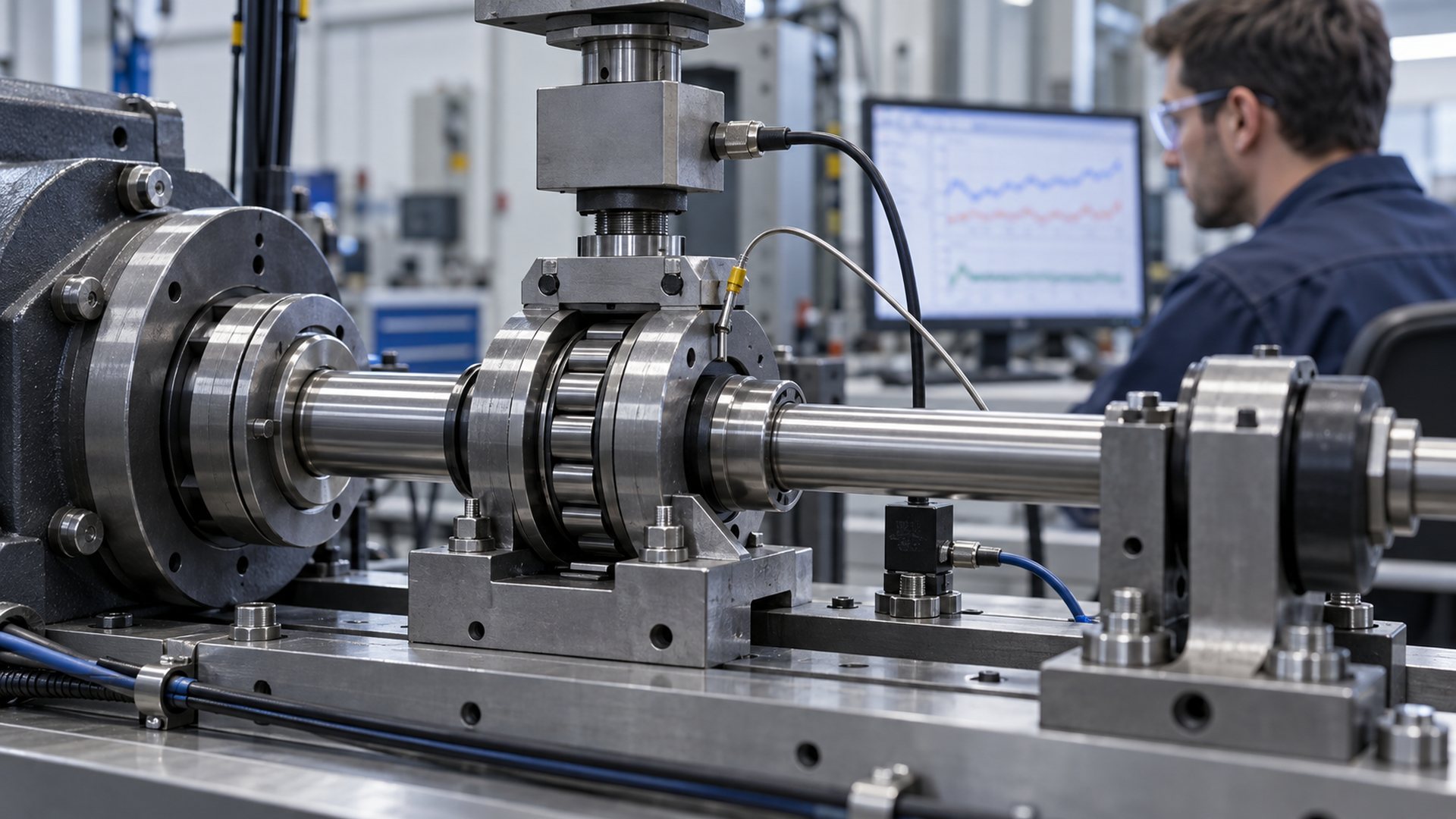
The equation is useful only when its inputs represent the installed condition. I would not insert the total machine weight directly as P. I first determine the reaction at each bearing, separate radial and axial components, account for load position, and use the selected bearing manufacturer's equivalent-load factors.
Variable duty needs more than one speed and one load. Start-up, steady travel, acceleration, reversal, dwell and impact may each contribute differently. The duty cycle should be divided into representative load and speed segments, then evaluated with the applicable manufacturer method.
Why Does Load Affect Bearing Life So Strongly?
Because load appears inside a power relationship, a modest change in equivalent load can produce a much larger change in calculated fatigue life.
For a ball bearing, the ratio C/P is raised to the third power. For a roller bearing, it is raised to the power 10/3. This does not mean every reduction in load produces the same improvement in field life. It means the fatigue calculation is highly sensitive to a correctly determined P.
Several design errors can make the real equivalent load higher than the value used in the calculation:
- dividing total load equally between rollers when frame deflection makes the distribution uneven;
- ignoring axial force from a groove flank, flange or misaligned belt;
- overlooking the moment from a roller mounted on a cantilevered stud;
- using average load while track joints, end stops or shocks create repeated peaks;
- assuming a stiff mounting when the axle or bracket bends;
- applying a nominal payload without including acceleration or tension forces;
- treating two bearings as equal load sharers without checking fits and support spacing.
Radial and axial bearing loads should be resolved from the actual shaft axis and contact geometry when the force direction is uncertain. Equivalent load should follow the bearing manufacturer's factors for the selected type, rather than a simple arithmetic addition of radial and axial loads.
Do Speed and Duty Cycle Reduce Bearing Life?
Speed mainly changes how quickly a given number of stress cycles is accumulated, while also changing lubrication, heat and seal behaviour.
If the calculated life in revolutions stays constant, doubling constant speed halves the corresponding operating hours. That simple conversion does not describe every physical effect. Higher speed can change lubricant film formation, churning, seal-lip heat and cage behaviour. Very low speed or oscillating motion may create different lubrication conditions because a stable separating film can be difficult to maintain.
Duty cycle matters because many mechanisms are intermittent. A sliding door roller may move slowly for short periods and remain stationary under load. A printer or packaging roller may accelerate and stop many times. A cable pulley may reverse direction. A conveyor guide roller may run continuously. Each application accumulates rotations and thermal cycles differently.
I normally request:
- operating and peak speed;
- percentage of time running;
- start-stop frequency;
- direction changes;
- time under stationary load;
- acceleration and braking conditions;
- expected operating hours or movement cycles;
- the required reliability or maintenance interval.
A low average speed does not automatically mean easy service. Oscillation, false brinelling during transport, shock while stationary and lubricant starvation can control performance even when total revolutions are limited.
How Do Lubrication and Contamination Change Life?
The rolling contacts need a suitable lubricant film, and particles or moisture can damage the surfaces long before a basic fatigue calculation predicts failure.
Lubricant selection is more than choosing “grease” or “oil.” The base oil viscosity at operating temperature, thickener compatibility, fill quantity, speed, load, seal arrangement and material compatibility all matter. Too little effective lubrication can allow damaging surface contact. Too much grease can increase churning and heat in high-speed arrangements. A lubricant can also age, bleed, oxidize or become contaminated during service.
The SKF Bearing Maintenance Handbook notes that lubricant effectiveness deteriorates through mechanical working, ageing and contaminant accumulation, and that contamination adversely affects bearing and seal service life.
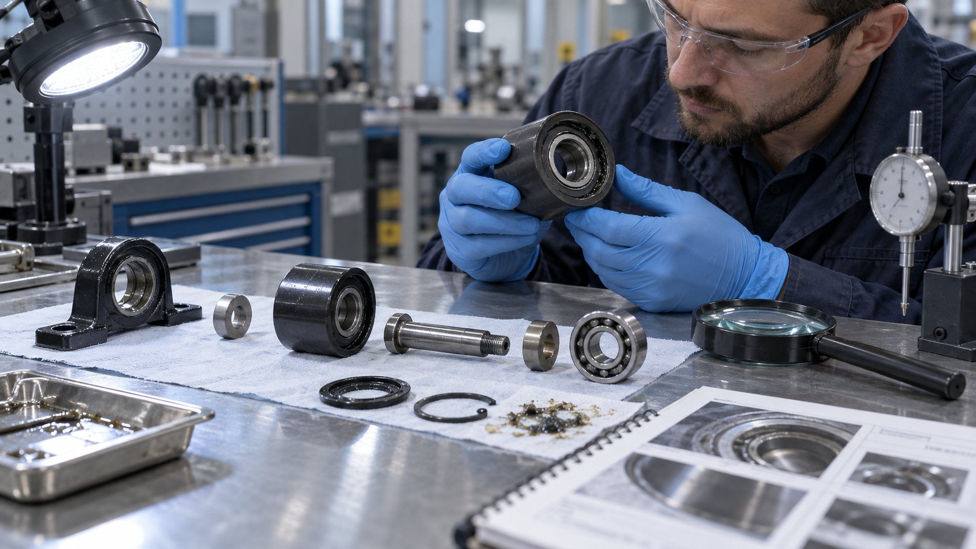
Closure choice changes the trade-off. A shield normally creates low closure friction but offers limited exclusion of fine contaminants or water. A contact seal provides a stronger barrier but can add torque and heat. The full comparison is covered in sealed versus shielded bearings.
For a roller assembly, I check the path by which dust, fibres, wash fluid or condensation can reach the bearing face. The wheel body may shield one side while leaving the axle side exposed. A spacer may rub a seal. A press tool may dent a shield. The closure designation alone does not describe this installed protection.
How Do Fits, Clearance and Alignment Affect Life?
Shaft and housing fits establish ring support and retention, but they also change internal clearance, load distribution and heat generation.
A ring that creeps on its seat can wear the mating surface and generate debris. Excessive interference can expand the inner ring or compress the outer ring, reducing internal clearance. If operating temperature creates a larger temperature difference between the rings, the remaining clearance can change again.
Insufficient operating clearance may increase torque, temperature and internal load. Excessive clearance can reduce stiffness and concentrate load on fewer rolling elements. The relationship is explained in HUNE's guide to bearing clearance and its installed effects.
Alignment also belongs in the life calculation boundary. Shaft deflection, non-parallel bracket plates, an angled bearing seat or a distorted wheel hub can produce edge loading that a simple radial-load model does not capture. Preload introduced by a short spacer or over-tightened fastener can have a similar effect.
The functional dimensions I normally control are:
| Interface | Functional control | Life-related risk if uncontrolled |
|---|---|---|
| Bearing bore to axle | Diameter, roundness, shoulder and retention | Creep, fretting, ring distortion or poor location |
| Bearing outside diameter to wheel or housing | Seat diameter, roundness, interference and support width | Reduced clearance, loose ring, cracked hub or uneven load |
| Bearing faces to spacer and bracket | Spacer length, shoulder diameter, side clearance | Seal rubbing or axial preload through rolling elements |
| Wheel tread or groove to bearing axis | Concentricity and radial runout | Cyclic load, vibration, noise and uneven tracking |
| Two-bearing arrangement | Seat coaxiality and support spacing | Misalignment and unequal load sharing |
| Roller to track | Profile match, contact position and track straightness | Axial force, impact and moment load |
Tighter tolerances are not automatically better. The drawing should tighten the dimensions that establish fit, alignment and running geometry, while leaving cosmetic and non-functional surfaces at economical process tolerances.
Why Can the Roller Assembly Fail Before the Bearing?
A bearing's calculated life does not guarantee the life of the wheel, axle, bracket or track, and those parts can also change the load applied to the bearing.
In a typical plastic-coated bearing roller, the load path is:
Track or cable → wheel tread or groove → wheel hub → bearing outer ring → rolling elements → inner ring → axle → bracket
Every interface can become the limiting element. A polymer wheel can wear, creep, crack or lose its intended profile. A hub can relax around the outer ring. An axle can bend. A spacer can transmit clamping through the wrong ring. A bracket can twist and create side load. A damaged track joint can add repeated impact.
This is why I separate bearing life from roller-system life. An integrated sliding roller with bearing must be selected by wheel material, running profile, bearing, axle and environment as one assembly. Likewise, the deep-groove ball bearing range is a starting point for envelope and bearing configuration, not a complete life approval.
The wheel's running diameter also affects bearing speed. For a given linear travel speed, a smaller running diameter turns faster. Groove contact diameter may differ from the nominal outside diameter, so the functional running diameter should be taken from the real track-contact geometry.
Which Failure Modes Are Outside Basic L10 Life?
L10 addresses rolling-contact fatigue under defined assumptions; it should not be used as a universal failure prediction.
Important failure or damage modes include:
- abrasive or adhesive wear;
- corrosion from water, condensation or chemicals;
- electrical erosion from current passing through the bearing;
- lubricant degradation or loss;
- contamination denting and surface distress;
- false brinelling from vibration while stationary;
- permanent indentation from static overload or impact;
- cage, seal or shield damage;
- ring fracture caused by fit, shock or defective support;
- excessive heat from preload, rubbing or speed;
- handling and installation damage.
Static loading needs a separate check. ISO 76:2006 specifies methods for basic static load rating and static equivalent load, with guidance on static safety factors for heavily loaded applications. A dynamic life calculation does not replace this static assessment.
Failure analysis should begin with evidence, not a single assumed cause. Record which surface failed, where the damage is located, whether the pattern follows the load zone, and what changed in torque, noise, temperature or lubrication. A teardown that discards the grease, seals or mating parts loses useful evidence.
How Should an OEM Validate Bearing Life?
Use the calculation to design the test, then validate the production-intent bearing inside the complete roller assembly under representative duty and environment.
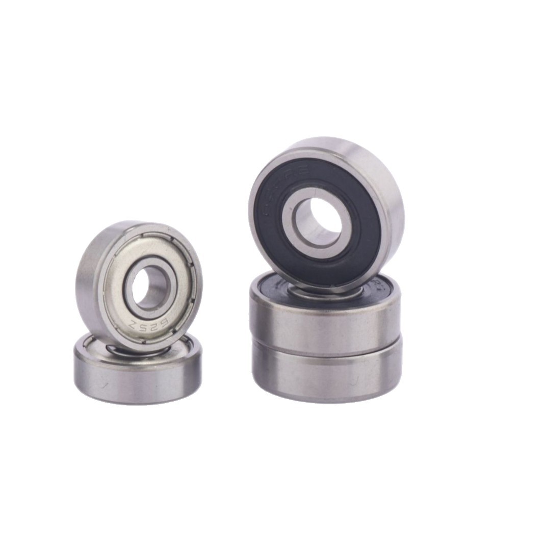
A practical validation plan can follow these stages:
- Define the life endpoint. State whether acceptance is based on fatigue, torque, noise, temperature, runout, wear, grease leakage or another equipment requirement.
- Map the load path. Draw radial, axial and moment loads from the track or cable through the wheel, bearing, axle and bracket.
- Calculate bearing reactions. Use actual geometry, support spacing, duty segments and the selected manufacturer's load factors.
- Check dynamic and static conditions. Evaluate fatigue life, peak load, impact and stationary load separately.
- Confirm the installed condition. Measure or verify shaft fit, wheel-seat fit, remaining clearance, retention, alignment and free-running torque.
- Test production-intent samples. Use the intended bearing, grease, seals, wheel material, moulding or machining process, axle, spacer and bracket.
- Run representative duty. Include load, speed, stops, reversals, environmental exposure and relevant worst-case alignment.
- Monitor useful indicators. Depending on the equipment, these may include torque, temperature, vibration, noise, tracking, runout and grease condition.
- Inspect after testing. Document wheel wear, fit movement, seal condition, lubricant contamination, raceway appearance and axle or bracket deformation.
- Control repeat production. Freeze the approved bearing designation, internal clearance, closure, lubricant, wheel material, fits, assembly method and inspection plan.
An accelerated test must preserve the failure mechanism it is meant to evaluate. Increasing load, speed or temperature simply to shorten test time can create a different failure mode. The acceleration method should be justified rather than treated as a universal multiplier.
What Should an OEM Buyer Send to a Supplier?
A useful bearing-life inquiry defines the operating system, the required endpoint and the mating geometry, not only a bearing number.
Send the supplier:
- application and roller function;
- assembly drawing showing bearing, wheel, axle, spacers, bracket and track;
- radial and axial loads at each operating condition;
- force location, cantilever distance and any applied moment;
- normal and peak speed or linear travel speed;
- duty cycle, starts, stops, reversals and time under stationary load;
- shock, vibration, transport and end-stop conditions;
- target life in hours, revolutions or equipment cycles;
- required reliability and the definition of end of life;
- temperature range and heat sources;
- dust, fibre, moisture, wash fluid or chemical exposure;
- bearing designation, closure, lubricant and internal-clearance requirement if already controlled;
- shaft and wheel-seat dimensions, fits, shoulder geometry and retention method;
- wheel material, running diameter, groove profile and mating-track drawing;
- acceptable torque, noise, runout, temperature rise or wear limits;
- sample-validation method and forecast production quantity.
If the loads are unknown, provide the mechanism geometry, moving mass, belt or cable tension, acceleration and support locations. A supplier can review a defined load case; it cannot derive reliable life from “heavy duty” or “long life” alone.
Discuss a Bearing Roller Life Requirement with HUNE
HUNE manufactures deep-groove ball bearings, plastic- and rubber-coated bearing rollers, wheel components and related OEM hardware. For life-sensitive projects, we can review the bearing together with the wheel profile, bearing seat, axle, spacer, bracket and mating track rather than treating the bearing as an isolated catalogue item.
Send your assembly drawing, load directions, speed, duty cycle, environment, required life endpoint, critical fits and forecast quantity through the HUNE contact page. HUNE's OEM development process can then be used to organise drawing review, sample approval and production controls around the actual application.
Frequently Asked Questions
Is L10 a guaranteed bearing service life?
No. L10 is a statistical rating life associated with 90% reliability under the calculation's stated assumptions. It does not predict the exact failure time of one bearing and does not include every failure mode. Actual service life can be limited by lubrication, contamination, corrosion, electrical damage, fit, alignment, shock or the surrounding roller assembly.
Does a larger bearing always last longer?
No. A larger bearing may have a higher dynamic load rating, but life still depends on equivalent load, speed, fit, lubrication and application geometry. Increasing bearing size can also reduce available wheel material, change running diameter or require a different shaft and housing. Compare the complete assembly and the selected manufacturer's data.
Does lower speed always increase bearing life?
Lower speed reduces the number of revolutions accumulated per operating hour, but it does not remove static load, shock, oscillation, contamination or lubricant-film problems. Very slow or short oscillating motion can have different lubrication requirements. Evaluate speed together with duty cycle and failure mechanism.
Can a sealed bearing run for its entire life without maintenance?
Some sealed bearings are supplied with grease intended for long service, but “sealed” does not mean immune to grease ageing, heat, contamination, water entry or seal damage. The expected grease life and closure suitability must be checked for the temperature, speed and environment, then verified in the installed assembly.
Which matters more for life: load or speed?
Both matter in different ways. Equivalent load has a strong power relationship with calculated fatigue life. Speed determines how quickly the calculated revolutions are accumulated and also affects lubrication and heat. A correct selection uses the actual load spectrum and speed or duty spectrum rather than choosing one variable as universally dominant.
Practical Engineering Recommendation
Calculate the bearing, but approve the system. Define the required life endpoint, determine the real reactions and duty cycle, check dynamic and static conditions, and then verify lubrication, contamination control, fits, clearance and alignment in a production-intent roller assembly. For sourcing, send the supplier the wheel–bearing–axle–bracket drawing together with the track geometry, loads, speed, environment and acceptance criteria. That information is the shortest path from a catalogue life estimate to a roller that meets the equipment requirement.


