

Pulley diameter and groove geometry affect bearing load in different ways. If cable tension and direction change remain identical, changing pulley diameter alone does not change the static resultant force at the axle. Diameter does change bearing speed, cable or belt bending, available bearing size and, in a torque-transmitting drive, the tension difference needed to transmit torque. Groove geometry determines where the flexible member contacts the wheel and whether forces remain centered or create side thrust, friction and uneven loading.
I therefore do not select a bearing from pulley outside diameter alone. I define the two span forces, direction-change angle, effective contact diameter, groove-to-cable or belt fit, axle position and bracket support. The bearing calculation comes after that complete load path has been established.
What Actually Loads a Pulley Bearing?
The bearing reacts the vector sum of the forces applied by the cable, belt, rope or track, together with wheel weight, acceleration and any side force.
The main load path is:
Cable or belt → groove or tread → pulley body and hub → bearing outer ring → rolling elements → inner ring → axle → bracket or machine frame
For an idler or direction-changing pulley, the flexible member normally pulls on the wheel along both free spans. Those two tension vectors combine into a resultant force at the pulley center. The bracket and axle then react that resultant.
Additional loads can enter through:
- pulley mass and acceleration;
- belt pretension;
- drive torque and unequal tight-side and slack-side tensions;
- cable or belt misalignment;
- flange rubbing;
- axial retention or assembly preload;
- impact from joints, splices or load changes;
- an overhung pulley position that creates axle bending moment;
- imbalance or tread runout at speed.
The bearing does not “see” the payload directly. It sees the reactions created by this geometry. HUNE's pulley-bearing engineering guide covers the broader relationship among bearing type, axle, hub, seals and operating environment.
How Does Cable Direction Change Become Bearing Load?
For equal tension on both spans, a larger direction change creates a larger resultant load at the pulley axle.
For a frictionless direction pulley with equal tension T on both sides, define δ as the change in cable travel direction:
R = 2T × sin(δ / 2)
Where:
- R is the resultant force applied to the pulley center;
- T is cable tension in each span;
- δ is the cable direction change, with 0° meaning no redirection and 180° meaning a complete reversal.
This definition matters. At 0°, the cable continues straight and the ideal resultant from redirection is zero. At 180°, both tension forces act in the same resultant direction and R = 2T. A diagram that uses the included angle between the two free spans may use a cosine form instead. The physics is the same, but the angle definition must be shown.
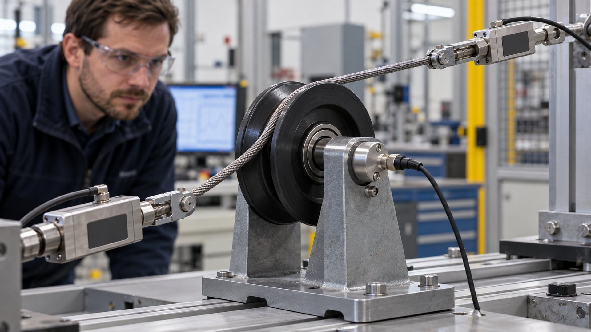
When the two span tensions differ, as in a drive pulley or a lossy system, calculate the vector resultant rather than using the equal-tension shortcut. With the same direction-change definition:
R = √(T1² + T2² − 2T1T2 cos δ)
The Timken Engineering Manual illustrates belt forces at pulleys and how external forces are resolved into bearing reactions. I use the selected bearing manufacturer's procedure after calculating the actual reactions at each support.
Does a Larger Pulley Reduce Bearing Load?
Not automatically. For the same two span tensions and the same direction change, the static resultant at the axle is independent of pulley diameter.
This is one of the most useful distinctions in pulley selection. Diameter is absent from the equal-tension resultant equation because force equilibrium depends on the tension vectors. Replacing a small idler with a larger idler does not by itself reduce the bearing reaction if tension and routing are unchanged.
Diameter can still change bearing duty indirectly:
- Bearing speed. At the same cable or belt linear speed, a smaller effective diameter rotates faster.
- Required tension difference in a drive. For a specified transmitted torque, increasing effective radius reduces the tangential tension difference required, subject to the belt system and traction conditions.
- Cable or belt bending. A larger diameter reduces curvature through each pass, while a small diameter bends the flexible member more sharply.
- Bearing envelope. A larger wheel can accept a different bearing size, wider hub or stronger rim section.
- Pulley-center position. Changing diameter may move the axle or cable line, altering the cantilever distance and bracket reaction.
- Mass and inertia. A larger wheel may add rotating mass and transient load, depending on material and construction.
The engineering answer therefore depends on what remains fixed. If torque, power, center distance or cable route changes with diameter, the span forces may also change. If all force vectors remain fixed, diameter changes speed and bending conditions but not the static resultant.
How Does Effective Diameter Change Bearing Speed?
Use the diameter at the real cable or belt contact, not the maximum flange diameter.
For a flexible member moving at linear speed v, pulley rotational speed can be estimated as:
n = 60v / (πDe)
Where:
- n is rotational speed in revolutions per minute;
- v is linear speed in metres per second;
- De is effective contact diameter in metres.
The effective diameter may be called running diameter, pitch diameter or tread diameter depending on the transmission type and standard. These terms should not be treated as universally interchangeable. A round cable sits below the outside flange. A V-belt runs at a defined datum or pitch position on the groove flanks. A timing belt uses its pitch line relative to the toothed pulley.
If the wrong diameter is used, calculated bearing speed, travel per revolution and torque relationship can all be wrong. The error becomes more significant when the groove is deep relative to pulley size.
How Does Diameter Affect Torque and Belt Tension?
In a torque-transmitting pulley, radius connects torque to the difference between tight-side and slack-side tension.
In a simplified belt drive:
M = (T1 − T2) × re
Where M is transmitted torque and re is effective radius. For a fixed torque, a larger effective radius requires a smaller tension difference. This can change bearing reaction, but total bearing load still depends on the vector directions and the baseline pretension in both spans.
A highly pretensioned belt can apply substantial radial load even when transmitted torque is low. Conversely, the tension difference that produces torque is not the same as the sum or vector resultant that loads the shaft. Power, speed, belt type, wrap, traction and service factor must be evaluated with the belt manufacturer's method.
The Gates Heavy Duty V-Belt Drive Design Manual distinguishes outside, datum and pitch-related sheave dimensions and provides defined groove geometry for V-belt systems. I would not substitute a visually similar groove or use outside diameter as the pitch diameter without confirming the applicable belt specification.
How Does Groove Geometry Change the Load Path?
Groove geometry determines contact position and local normal forces; mismatch or misalignment can turn a mainly radial load into combined radial and axial bearing load.
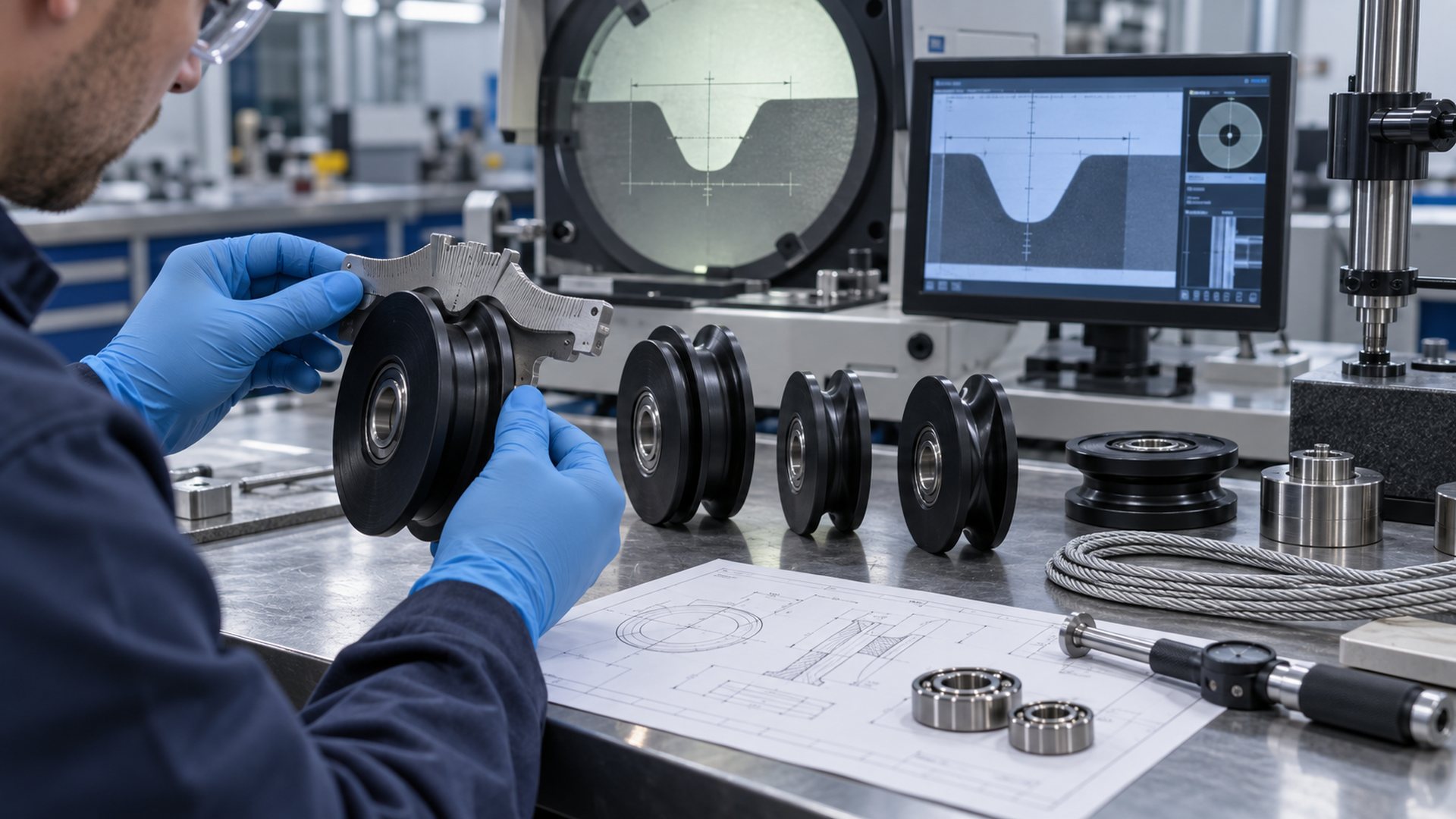
The groove controls where the cable, belt, rail or track touches the pulley. That contact position establishes effective diameter and influences whether the resultant passes near the bearing center plane.
A symmetric cable centered in a matching U-groove can produce a mainly radial reaction. If the cable approaches at an angle, rides one flange or is pinched by a narrow groove, one side of the wheel carries more contact force. The bearing may then receive axial load or a tilting moment through the hub.
For a V-groove, the two flanks produce inclined normal forces. When contact is symmetric, their side components balance at the pulley level. They still create local contact pressure and rim stress. If belt position, groove angle, wear or alignment is asymmetric, the balance changes and side force can reach the bearing and bracket.
The load calculation must distinguish:
- the external resultant determined by span forces;
- the local contact forces between flexible member and groove;
- the bearing reactions created by support spacing and load position;
- the axial or moment component created by off-center contact.
HUNE's guide to why guide wheels use grooved profiles explains how U-, V- and flanged profiles control lateral guidance. A guide wheel running on a rigid rail is a different contact problem from a sheave supporting a flexible rope, even when both parts are called pulleys.
What Happens When a U-Groove Does Not Match the Cable?
A mismatched U-groove can pinch the cable, let it wander or force it against a flange, changing friction, wear and side loading.
If the groove is too narrow or has an unsuitable root radius, the cable may contact high on both sides, wedge into the profile or become compressed. If the groove is too wide, the cable may move laterally and strike the flanges during direction changes. A groove that is too shallow may offer limited retention; excessive depth may increase flange contact or complicate release and cleaning.
For wire-rope sheaves, the correct dimensions depend on the rope and governing application standard. Crosby's McKissick sheave groove-profile guidance shows that groove angle, groove radius, tread depth and pitch-diameter relationships are controlled features, with different profiles used for different applications. Those published values should not be transferred automatically to coated cable, fibre rope, timing belt or a plastic guide roller.
For a custom HUNE U-groove bearing pulley, the mating cable or rail diameter belongs in the drawing review together with wheel diameter, width, bearing and axle. A nominal groove label alone does not define the contact.
How Do Misalignment and Fleet Angle Affect the Bearing?
When a cable or belt enters the pulley outside its intended plane, flange contact and axial bearing load can develop.
The pulley plane should coincide with the flexible member's intended path. Shaft skew, bracket twist, changing take-up position or poor machine alignment can move the span laterally. The cable or belt then contacts one groove wall or flange before it reaches the intended central contact band.
Consequences can include:
- axial force on the bearing;
- uneven groove and flange wear;
- cable abrasion or belt edge damage;
- increased torque and heat;
- oscillating side load as the pulley turns;
- migration of the belt or cable from the groove;
- bracket deflection that makes alignment progressively worse.
I do not approve a pulley only by spinning it freely on a bench. It should be checked in the installed span geometry over the full machine travel, including the worst lateral position and bracket deflection.
How Do Bearing Position and Bracket Geometry Change the Reaction?
The same pulley resultant can create very different bearing and axle stresses depending on where the force acts relative to the supports.
If the groove centerline is offset from the bearing reaction plane, the load creates a moment:
M = R × e
Where e is the perpendicular offset between the resultant force line and the relevant support plane. A cantilevered pulley on a long stud can therefore bend the axle and tilt the bearing even when the resultant force is moderate.
With two bearings, load sharing depends on the distance between bearing reaction planes, bearing fits, axle stiffness and seat alignment. Adding a second bearing does not automatically double pulley capacity. It can improve moment support when the arrangement is designed and manufactured to distribute load.
The choice between a bearing-integrated wheel and a plain bore also changes the interface. HUNE's comparison of a pulley wheel with bearing and a plain-bore pulley explains the differences in friction, shaft requirements, replaceability and assembly control.
How Is Pulley Load Converted into a Bearing Calculation?
Calculate support reactions first, then convert radial and axial components into the equivalent load for the selected bearing.
A practical sequence is:
- Define tension in each span for every operating condition.
- Draw the cable or belt directions and calculate their vector resultant.
- Add pulley weight, acceleration, side forces, shocks and other external loads.
- Locate the force relative to the bearing or bearing pair.
- Calculate radial, axial and moment reactions at each bearing.
- Use the selected manufacturer's equivalent-load factors and life method.
- Check static load and peak or impact conditions separately.
- Confirm speed from effective diameter and linear velocity.
- Verify lubrication, seals, fits, clearance and temperature.
- Check wheel, hub, axle and bracket strength separately from bearing rating.
For a radial bearing under combined loading, a common catalogue form is P = XFr + YFa, but the factors X and Y are specific to bearing type and operating condition. They should come from the selected manufacturer's current data.
ISO 281:2007 specifies methods for rolling-bearing dynamic load ratings and rating life. It does not establish the capacity of the complete pulley, hub, axle and bracket, and its scope does not cover every service-life mechanism such as wear, corrosion or electrical erosion.
Which Pulley Dimensions Are Functional?
The drawing should control contact, rotation and support geometry separately.
| Dimension or control | Functional purpose | Common sourcing error |
|---|---|---|
| Effective or pitch diameter | Sets speed, travel and torque relationship | Using maximum outside diameter |
| Maximum outside diameter | Controls package clearance and flange envelope | Treating it as the running diameter |
| Groove root radius or flank profile | Matches cable, rope, belt or rail contact | Specifying only “U-groove” or “V-groove” |
| Groove angle | Controls V-profile contact and wedging | Copying an angle from another belt system |
| Groove depth and flange height | Supports retention and clearance | Assuming deeper always guides better |
| Groove centerline to bearing datum | Controls offset and moment load | Omitting the axial location of contact |
| Bearing bore, outside diameter and width | Defines axle and hub interface | Selecting by bore alone |
| Bearing-seat fit | Retains and supports the bearing | Ignoring moulding shrinkage or coating pressure |
| Tread or groove runout | Controls cyclic load and vibration | Measuring only the uncoated bearing |
| Wheel and bearing-face width | Controls spacers and bracket clearance | Allowing washers to rub the wheel or seal |
| Axle support span and cantilever distance | Controls bending and bearing reactions | Supplying the pulley drawing without the bracket |
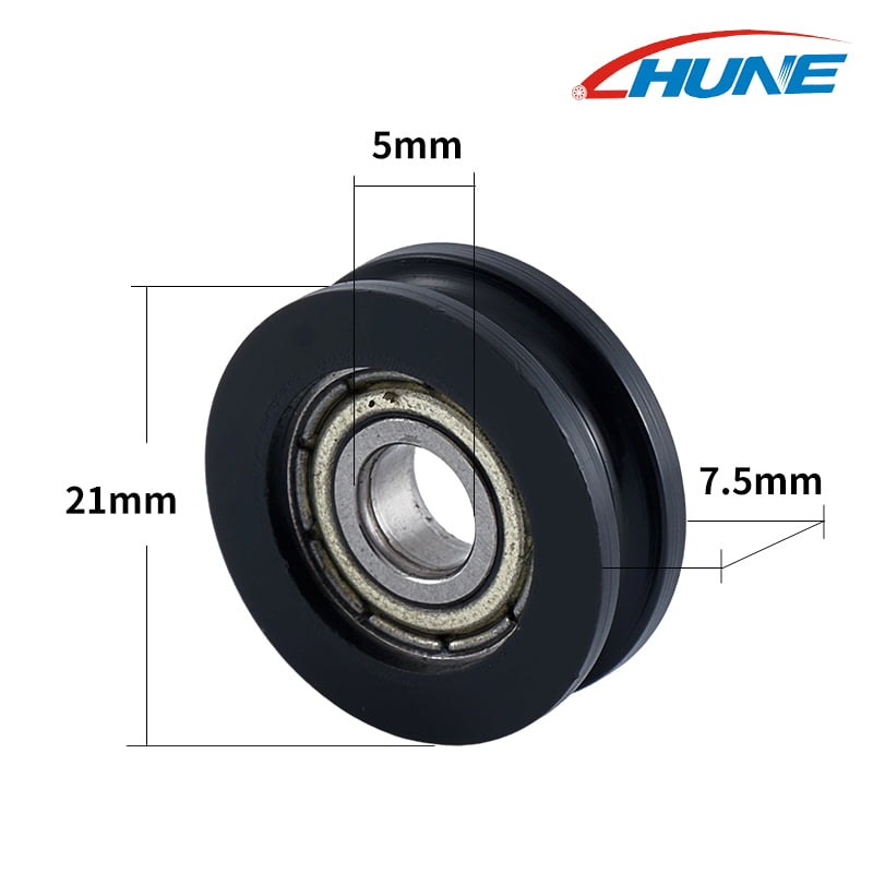
For moulded plastic or coated pulleys, material shrinkage, bearing insertion and secondary machining can change the finished groove and bearing seat. HUNE's bearing-roller material and process overview describes why bearing selection, outer material, moulding and final assembly should be coordinated rather than sourced as unrelated operations.
How Should an OEM Validate Pulley Geometry and Bearing Load?
Validate the production-intent pulley in the real span geometry, then inspect the contact pattern and bearing condition.
A useful validation plan includes:
- Requirement review. Define flexible-member type, size, construction, tension, direction change, speed, duty and environment.
- Load model. Calculate span-force vectors, bearing reactions, overhung moment and peak conditions.
- Geometry sample. Check seating, release, flange clearance and effective diameter with the actual cable, belt or rail.
- Dimensional inspection. Measure groove profile, bearing-seat fit, concentricity, runout, width and contact-center offset.
- Installed test. Run the intended bracket, axle, spacer and pulley through normal and worst-case alignment.
- Duty test. Include starts, stops, reversals, shock and environmental exposure representative of service.
- Teardown. Inspect groove wear, cable or belt damage, bearing torque, grease, seals, fit movement and bracket deformation.
- Production approval. Freeze the approved drawing, material, bearing designation, process, inspection method and revision.
Accelerating a test by increasing tension or speed can change the failure mechanism. Any acceleration factor should be justified for the feature being evaluated rather than applied as a general shortcut.
What Should a Buyer Send to the Pulley Supplier?
A useful RFQ includes the complete span geometry and mating profile, not only pulley outside diameter and bore.
Send:
- application and pulley function;
- cable, rope, belt, rail or track specification;
- mating-member diameter or cross-section drawing;
- tension on each span under normal and peak conditions;
- direction-change angle and a sketch of both span directions;
- linear speed, starts, stops, reversals and duty cycle;
- transmitted torque or power if applicable;
- effective diameter requirement and maximum package diameter;
- groove radius, angle, depth, flank profile and flange requirements;
- bearing designation or required bore, outside diameter and width;
- axle, spacer, retention and bracket drawing;
- offset from groove centerline to bearing support plane;
- material, hardness or surface requirements where applicable;
- environment, temperature, moisture, dust and chemicals;
- acceptable torque, noise, runout, wear and service-life endpoint;
- sample-validation method and forecast quantity.
The sliding rollers with bearing range can provide construction references, but an existing wheel should only be selected after its functional contact geometry and bearing arrangement match the application.
Discuss a Custom Bearing Pulley with HUNE
HUNE manufactures deep-groove ball bearings, plastic- and rubber-coated bearing rollers, U-groove pulley wheels and related OEM hardware. We can review the wheel, bearing, axle, spacers, bracket and mating cable, belt or rail as one load path.
Send the assembly drawing, span directions, tensions, effective diameter, groove profile, operating speed, environment and expected quantity through the HUNE contact page. These details make it possible to compare an existing pulley structure with a drawing-based custom part and define a meaningful sample-validation plan.
Frequently Asked Questions
Does a larger pulley always reduce bearing load?
No. With identical span tensions and direction change, static resultant force at the axle does not depend on pulley diameter. A larger diameter changes rotational speed, flexible-member bending and bearing package options. In a torque-transmitting drive, it can also change the tension difference required for a specified torque, so the whole system must be recalculated.
Does a deeper groove increase pulley load capacity?
Not by itself. Groove depth influences retention and flange geometry, while capacity depends on material, rim section, hub, bearing, axle, bracket and the actual contact pattern. An unnecessarily deep or mismatched groove can encourage flange contact, trapping or poor release without improving the bearing rating.
Is pulley outside diameter the same as pitch diameter?
Usually not. Outside diameter describes the maximum wheel envelope. Pitch, datum, tread or effective diameter refers to a defined contact or motion line and depends on the cable, rope or belt system. The drawing and applicable supplier standard should state which diameter controls speed and torque calculations.
Can one U-groove pulley work with several cable diameters?
Possibly, but compatibility should not be assumed. Different cable diameters sit at different depths, changing effective diameter, side clearance and contact. A cable that is too large may wedge or ride high; one that is too small may wander or contact the groove root differently. Validate every intended combination.
Does a double-bearing pulley have twice the load capacity?
No. Two bearings can improve support spacing and moment resistance, but load sharing depends on seat alignment, shaft and hub stiffness, fits and external force position. The wheel, axle and bracket can remain the limiting parts. Calculate the reactions at each bearing and validate the complete assembly.
Practical Engineering Recommendation
Start with the two span-force vectors, then define the contact geometry. Calculate the resultant from real tension and direction change, use the effective diameter for speed and torque, and locate the groove contact relative to the bearing supports. After selecting the bearing, validate the finished wheel, bearing, axle and bracket with the actual cable, belt or track. For sourcing, send the supplier the mating profile and complete pulley arrangement so the quoted part is based on the same load path you intend to manufacture.


