

Why do guide wheels use grooved profiles instead of a simple flat running surface? The groove gives the wheel a defined relationship with its rail, cable or track.
Short engineering answer: a grooved guide wheel controls lateral position by contacting selected sides of a matching track. A U-groove can cradle a round rail or cable, a V-groove can locate on angled flanks, and flanges can limit side movement while the center tread carries the main load. The groove also defines the contact points, effective running diameter and side-force path.
The benefit only appears when the groove matches the mating geometry. A wrong radius, angle, depth or clearance can concentrate stress, increase friction, create noise or allow the wheel to wobble. I therefore select the wheel and track as one interface rather than choosing a groove from appearance alone.
What Does a Groove Actually Do?
A groove converts a wheel from a simple rolling support into a component that can also guide position.
A flat roller mainly reacts to load normal to its running surface. It can carry a panel, carriage or product, but another part usually has to control lateral movement. A grooved wheel wraps partly around a rail or contacts two angled surfaces. Those contacts create reactions that oppose sideways displacement.
Depending on the system, a groove can:
- keep a wheel centered on a rail;
- keep a cable or cord inside a defined path;
- control lateral movement of a door, carriage or moving fixture;
- establish repeatable contact points;
- provide side-force capacity through the wheel profile;
- reduce reliance on a separate guide surface;
- define the effective running radius and travel ratio.
Grooving does not automatically improve every roller. It reduces freedom of movement, so the rail position, wheel alignment and production tolerances become more important.
Which Grooved Profiles Are Common?
Each groove shape solves a different contact problem and needs a matching track profile.
| Wheel profile | Typical mating surface | Primary function | Main compatibility risk |
|---|---|---|---|
| Flat | Flat rail, channel floor or product surface | Vertical support with low lateral constraint | Side drift unless another guide is present |
| U-groove or round groove | Round rail, tube, cable, rope or cord | Cradles a rounded mating surface and limits sideways movement | Wrong radius creates edge contact or excessive play |
| V-groove | V rail, angle edge or two inclined track flanks | Produces two-sided location and a defined center path | Angle mismatch, root contact or uneven flank loading |
| H-groove or double-flange | Narrow flat rail or guided strip | Central tread supports the load while side walls retain the track | Flange rubbing if rail width or alignment varies |
| Single-flange | Flat rail with one controlled side | Provides one-sided lateral reference | Requires a separate opposing constraint if movement can reverse |
| Crown or convex tread | Flat track with expected small alignment variation | Reduces sensitivity to edge loading | Does not positively locate the wheel laterally like a groove |
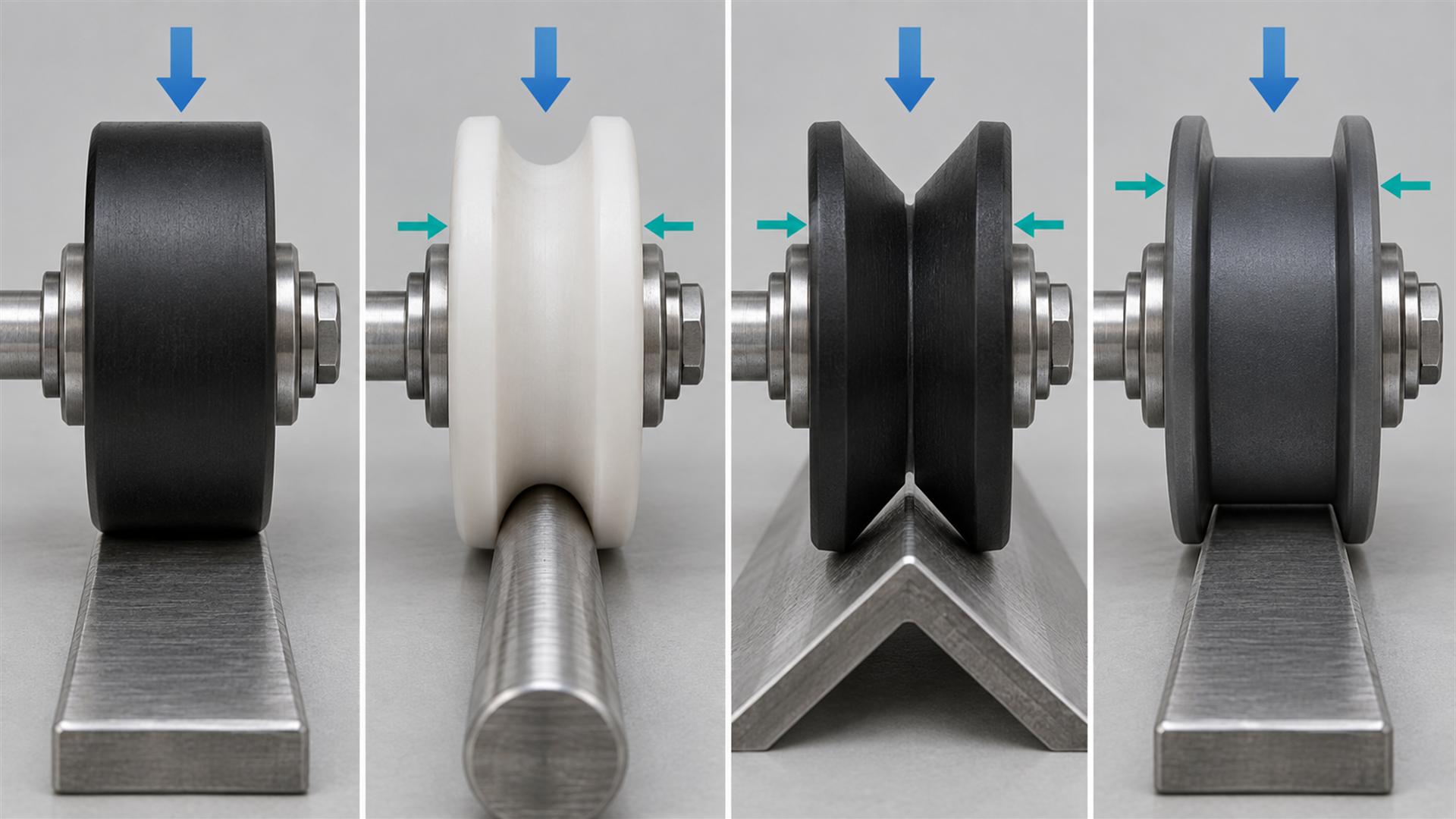
Schaeffler's technical guide to track rollers distinguishes cylindrical, crowned and profiled running surfaces. It notes that crowned surfaces are used where misalignment may occur, while profiled concave outer raceways can be used in robust shaft-guidance systems. This supports a practical point: “profiled” is a family of design choices, not one universal geometry.
How Does a Groove Control Lateral Position?
Side guidance comes from the direction of the contact reactions, not from the groove name.
On a V-profile, the two inclined contact faces react to vertical load and oppose side movement. On a U-profile, the round rail contacts the curved groove at positions determined by the relative radii and load. With flanges, the center tread may carry normal running load while a flange engages only when side movement reaches its clearance.
I first mark the intended contact points on a cross-section. Then I ask:
- Which surface carries the main radial load?
- Which surface reacts to a lateral force?
- Does the groove run with continuous two-sided contact or controlled clearance?
- Can the track touch the groove root?
- Will a flange carry load continuously or only during lateral displacement?
- Where is the contact line relative to the bearing center?
These questions show whether the profile will guide smoothly or create unnecessary sliding and edge stress.
How Does Groove-to-Track Fit Affect Contact?
The groove radius or angle must create the intended contact zones while preserving the required clearance.
A U-groove that is too tight around a round rail can contact near sharp upper edges, wedge onto the rail or become sensitive to diameter variation. A groove that is too wide may touch only near its bottom and provide weak lateral control. A well-matched profile normally uses controlled flank contact without forcing the rail into the groove root.
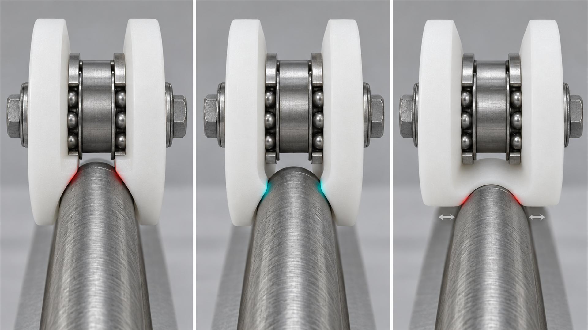
The exact contact area changes under load because real materials deform elastically. NASA's technical treatment of rolling-contact geometry explains that contact stress depends on load, material properties and the relative curvature of the two bodies. I use that principle qualitatively here: changing the groove or rail radius changes more than appearance; it changes the contact condition.
For V-grooves, the same reasoning applies to groove angle, rail angle, tip radius and root clearance. A wheel should run on the intended flanks, not bottom out on the rail apex unless the system is specifically designed for that contact.
Why Does the Effective Running Diameter Matter?
The largest outside diameter of a grooved wheel may not be the diameter that controls travel.
The effective running diameter is measured through the actual contact points. A deep U-groove wheel may have large flanges, while the rail contacts much closer to the wheel center. A V-wheel contacts its mating track on two angled flanks. If an engineer uses the maximum outside diameter to calculate travel, speed or installed height, the result may be wrong.
I normally define:
- maximum outside diameter for packaging clearance;
- effective running diameter at the intended track contact;
- groove root diameter where relevant;
- bearing center height in the installed bracket;
- door, panel or carriage height created by the complete wheel-and-track stack.
For systems with synchronized rollers, encoders, belt drives or print-media transport, the effective diameter can affect speed ratio and distance per revolution. It should be derived from the real contact geometry and confirmed by system testing.
Is a Deeper Groove Always Better?
No. Greater depth can improve retention, but it can also increase interference risk and reduce useful wheel material around the bearing.
A deep groove may help keep a cable or round rail captured, particularly when side displacement must be limited. However, the track still needs entry clearance, manufacturing tolerance and room for misalignment. If the groove side walls are too close, the wheel can rub or wedge. If the groove reaches too close to the bearing seat, the remaining polymer wall may become too thin for the intended load and production process.
The correct depth depends on:
- required retention and possible side movement;
- rail, cable or cord diameter variation;
- track alignment and bracket adjustment;
- wheel material and wall thickness;
- bearing outside diameter and seat geometry;
- moulding draft or machining allowance;
- contamination and debris escape path.
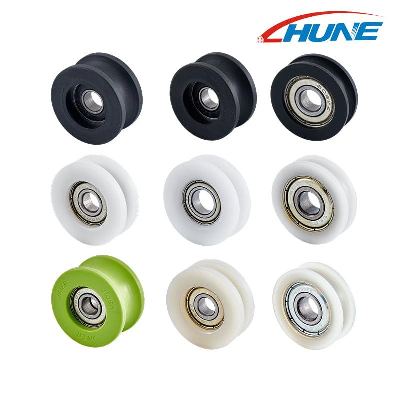
HUNE's U-groove bearing sliding rollers illustrate several sizes and material configurations. For a complete purchasing workflow, the related U-groove roller selection guide explains what an OEM should provide for track matching.
When Does a V-Groove Make More Sense?
A V-groove is useful when a matching angled rail should define a repeatable center path through two flank contacts.
V-guides are common in machine doors, automation, material handling and other linear systems. The geometry can provide strong lateral location, and adjustable eccentric mounting is often used to control fit in multi-wheel carriages. HepcoMotion describes its V-guide technology as a wheel-and-track system with self-aligning and debris-shedding behaviour. Those properties belong to the complete designed system, not to any V-shaped wheel on any angle bar.
For an OEM V-groove roller wheel with a bearing, I would confirm:
- included groove angle and matching rail angle;
- flank contact position;
- clearance at the rail apex and groove root;
- rail corner radius and surface finish;
- preload or running clearance in a multi-wheel arrangement;
- allowance for track straightness and mounting variation.
An angle match on the drawing is only the start. The installed assembly determines whether both flanks share contact as intended.
What Problems Can the Wrong Groove Cause?
Groove mismatch changes contact, guidance and bearing loading at the same time.
| Observed behaviour | Geometry to inspect first | Possible mechanism |
|---|---|---|
| Wheel wobbles sideways | Groove width, rail diameter and flange clearance | Too much lateral clearance or weak flank engagement |
| Roller feels tight in part of the travel | Track alignment, groove depth and root clearance | The rail wedges or bottoms as geometry changes |
| Wear appears on one groove edge | Wheel alignment, bracket position and side load | One-sided contact or skewed running |
| Repeated noise once per wheel revolution | Running-surface runout, mould parting line or local damage | Contact position varies cyclically |
| Track or cable wears rapidly | Radius match, material pair and surface finish | Concentrated contact or excessive sliding |
| Bearing becomes rough early | Load line, side force, axle alignment and fit | Groove-generated side reaction reaches the bearing improperly |
| Door or carriage drifts | Profile type, guide arrangement and track spacing | The system lacks enough lateral constraint |
The guide on why sliding furniture doors wobble shows the same system principle in furniture hardware: a wheel can rotate freely yet fail to control the panel because the guide-to-track geometry is wrong.
How Do Material and Bearing Choices Interact with the Groove?
The groove defines external contact, while the material and bearing determine how that contact is carried through the wheel.
POM, nylon, PU and metal running surfaces can respond differently to load, moisture, impact, debris and noise requirements. The exact grade, hardness, additives and wall thickness matter. A soft or compliant tread may change its contact patch under load; a hard material may hold geometry more closely but transmit more vibration to the structure.
Inside the wheel, a ball bearing separates rotation from the fixed axle. The bearing does not correct an incompatible groove. Conversely, a good groove does not correct excessive bearing play, poor retention or axle misalignment. The overview of bearing roller construction explains how the outer wheel, bearing, axle, bracket and track form one load path.
I normally check whether the groove creates radial load, axial load, tilting moment or a combination at the bearing. Side contact on one flange can place the bearing in a different condition from a centered radial load.
Which Dimensions Should the OEM Drawing Control?
The drawing should define the mating profile and intended contact, not only wheel diameter and bore.
For a grooved guide wheel, likely functional dimensions include:
- bearing bore, outside diameter and width;
- maximum wheel outside diameter;
- effective running diameter;
- overall wheel width;
- groove width at a defined datum;
- groove depth;
- groove radius or included angle;
- groove-root radius and required root clearance;
- flange thickness and edge radius;
- concentricity or runout of the running profile to the bearing bore;
- bearing-seat diameter, depth and retention;
- wheel-center position relative to the axle or bracket datum.
The track drawing should show its radius, angle, width, corner condition, material, finish and mounting datum. If the wheel and track come from different suppliers, both must work from the same controlled section.
I avoid applying a tight tolerance to every cosmetic face. The useful controls are the dimensions that establish contact, clearance, installed height and rotation.
How Does Manufacturing Method Affect the Groove?
Moulding and machining can both produce useful grooves, but they create different tooling, tolerance and surface considerations.
An injection-moulded groove may be economical for repeat demand. The design must account for mould release, parting-line location, shrinkage, bearing insertion and any post-mould dimensional change. A parting line across the running surface can affect noise if it is not controlled.
Machining can be practical for prototypes, lower quantities or a profile change based on an existing wheel blank. It also allows a groove to be cut after moulding when sufficient material remains. However, machining cannot create wall thickness that the original blank does not have, and deep cutting may approach the bearing seat.
For a moulded-plus-machined route, the drawing should distinguish:
- mould-controlled surfaces;
- machined running surfaces;
- bearing-seat datums;
- allowed machining stock;
- inspection stage before and after bearing assembly.
The purchasing decision should compare tooling, machining time, scrap risk, inspection, expected annual demand and future profile changes rather than unit price alone.
How Should Grooved Guide Wheels Be Validated?
Test the wheel in the real track with the actual bracket, load direction and alignment variation.
A practical OEM approval sequence is:
- Interface review: mark intended contact and clearance on wheel and track sections.
- Geometry sample: verify insertion, engagement, installed height and free movement.
- Material confirmation: approve the wheel compound, bearing, axle and track material.
- Contact review: inspect where the loaded wheel actually touches the track.
- Installed motion test: check operating force, lateral movement, noise and runout across full travel.
- Variation test: include realistic track straightness, joints, bracket adjustment and production samples.
- Pilot production: confirm repeatability of groove dimensions, bearing seat and assembled runout.
A free-spinning wheel on a bench only confirms basic rotation. It does not validate groove-to-track compatibility.
What Should a Buyer Send the Supplier?
A useful enquiry includes both cross-sections and explains what the groove must control.
Send:
| Information | What to include |
|---|---|
| Application | Door, window, elevator mechanism, printer, conveyor, cable guide or machine carriage |
| Guided element | Round rail, tube, rope, cable, V-track, angle edge or flat strip |
| Track | Dimensioned cross-section, material, finish, straightness requirement and physical sample if available |
| Wheel | Outside diameter, width, groove profile, bearing and axle or stud |
| Load | Direction, point of application, number of wheels, side load and impact condition |
| Space | Bracket width, axle support, installation envelope and adjustment range |
| Performance | Speed, duty cycle, permitted lateral movement, noise and operating-force target |
| Environment | Dust, moisture, chemicals, temperature and cleaning exposure |
| Purchasing | Prototype quantity, first order, annual demand and expected design revisions |
If a track drawing is unavailable, I prefer a short track sample together with the old roller and bracket. A front photograph does not show radius, angle, root clearance or effective running diameter reliably.
Frequently Asked Questions
Do grooved guide wheels carry load as well as guide movement?
They can, but the function depends on the system. A bottom V-groove wheel may carry vertical load and provide lateral location. A small upper U-groove wheel may guide position while another roller carries the main weight. The drawing should identify which surfaces carry load and which only limit movement.
Is a U-groove the same as a round groove?
Suppliers sometimes use the terms interchangeably, but the label does not define radius, width or depth. Two wheels both called U-groove may contact the same rail differently. Compare dimensioned cross-sections and intended contact points before treating them as equivalent.
Can one grooved wheel fit several rail diameters?
Possibly, if the system allows different clearances and contact positions, but compatibility should not be assumed. Changing rail diameter changes where it sits in the groove, the lateral freedom and the effective running diameter. An OEM should validate each intended combination.
Does a bearing make groove matching less important?
No. The bearing controls rotation around the axle. The groove controls how the wheel contacts and follows the track. A low-friction bearing inside a mismatched groove can still produce edge loading, side play, noise or binding.
Select the Groove from the Mating Geometry
The best guide-wheel profile is the one that creates the required contact and lateral control on the real track without unwanted interference.
Start with the rail, cable or track cross-section. Define the intended contact points, running diameter, guidance direction and clearance. Then select the wheel material, bearing, axle, bracket and manufacturing route around that interface. A standard U- or V-groove can be efficient when it matches; a custom profile is justified when the mating geometry or performance target cannot be served by an existing wheel.
HUNE manufactures plastic-coated bearing rollers, grooved guide wheels, shafts, brackets and related components for OEM sliding and guiding systems. To review a project, send the wheel and track cross-sections, intended load direction, bearing and mounting arrangement, critical dimensions, environment, samples if available and expected quantity through the HUNE contact page. These details make it possible to evaluate the groove as part of the complete roller system.


