

Why do sliding furniture doors wobble even when the rollers still turn freely? In most cases, the problem is not the wheel alone. Wobble appears when the door has too much freedom to move sideways or rotate within the complete system.
Short engineering answer: a sliding furniture door wobbles when its guide clearance, roller alignment, track geometry, bracket stiffness or panel rigidity cannot control lateral movement. The load-bearing rollers support the door, while a separate guide normally keeps it upright and aligned. If either function is weak or inconsistent, the panel can sway, rock or knock against the cabinet during travel.
For an OEM project, I therefore review the door, rollers, guides, brackets, tracks and cabinet structure as one mechanism. This article explains where movement begins, which dimensions control it and what a buyer should validate before approving production.
Which Parts Control Door Stability?
A stable sliding furniture door needs one structure to carry the load and another to control lateral movement.
In a bottom-running system, the lower roller carriages support the door's vertical weight. The upper guide keeps the panel from leaning toward or away from the cabinet. In a top-hung system, the upper carriers support the weight and a lower guide limits swing. The hardware arrangement changes, but the two functions remain separate.
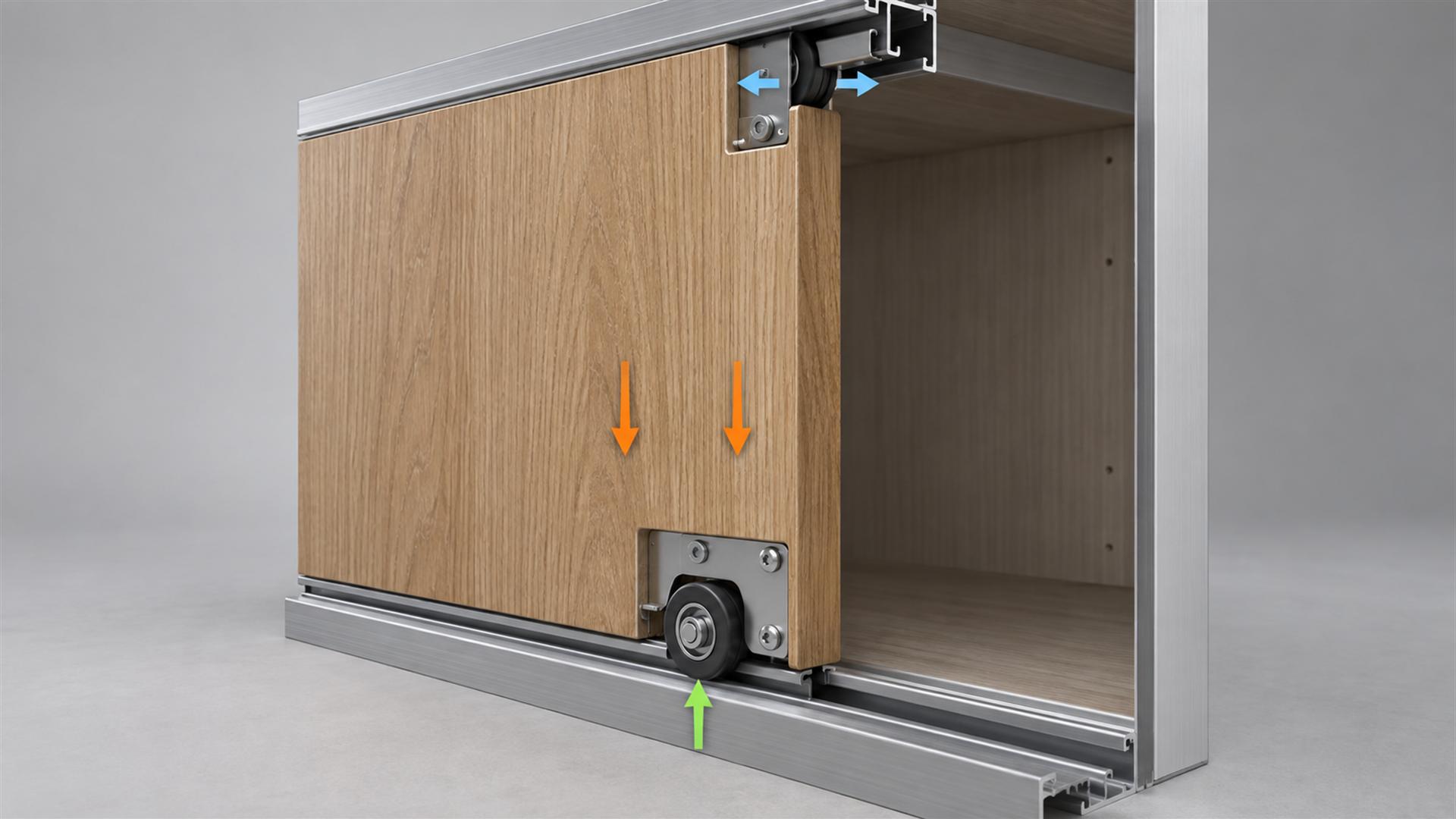
The Element Designs sliding-door technical manual, for example, identifies top door guides separately from the bottom carrier and load-bearing roller system. Hettich likewise sells SlideLine M as a set of running and guide components. These manufacturer documents support an important design point: a roller that carries weight does not automatically control every direction of movement.
I normally divide the system into six functional groups:
- Door panel: mass, height-to-width proportion, flatness and torsional stiffness.
- Load-bearing rollers: wheel profile, bearing or bushing, installed height and load sharing.
- Anti-sway guides: wheel or guide block position, engagement and lateral working clearance.
- Tracks: profile width, straightness, parallelism, joints and fixing support.
- Brackets and fasteners: stiffness, adjustment range, mounting-hole location and resistance to loosening.
- Cabinet structure: squareness, shelf deflection, base support and movement after assembly.
This is why replacing a visible wheel without checking its mating track may leave the wobble unchanged.
How Does Guide Clearance Create Wobble?
Too much lateral clearance permits sway, while too little clearance can make the door bind. The target is controlled working clearance.
An upper guide needs enough space to enter the track and move through normal cabinet variation. It also needs to limit side displacement before the tall door panel develops noticeable angular movement. A small change at the guide can become a much larger movement at the opposite edge of a tall panel.
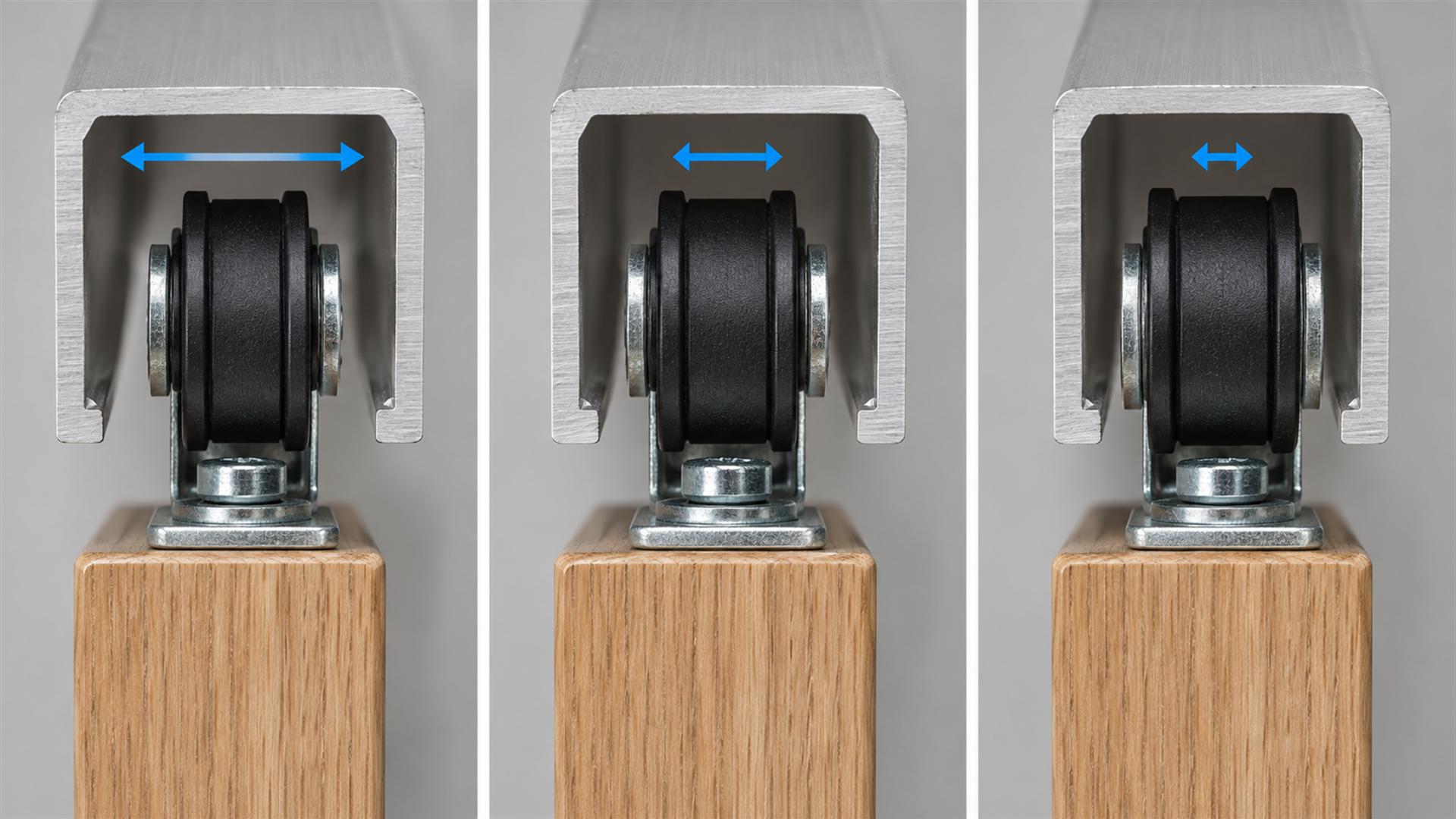
I do not specify “zero play” as a general solution. A guide that is preloaded too tightly against both sides of a channel can raise operating force, transmit track variation into the panel and create sticking. A loose guide may run freely but fail to control the door. The correct clearance depends on the guide construction, track profile, panel size, manufacturing variation and environmental change.
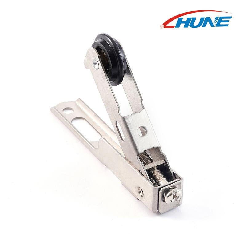
For an adjustable anti-sway top guide roller for wardrobe doors, the wheel position and bracket adjustment are part of the functional interface. Wheel outside diameter alone does not define whether the assembly will guide the door properly.
Why Can a Door Rock Even with a Good Upper Guide?
Diagonal rocking often begins at the load-bearing rollers, the lower track or the panel mounting points.
Two lower rollers should place the door at the intended height and share the load as the design requires. If one roller sits higher, its bracket flexes more or its wheel contacts a different part of the track, the door can pivot around the more heavily loaded support. The upper guide then reacts to movement that started below.
Likely causes include:
- unequal roller center heights;
- different adjustment settings between left and right carriages;
- wheel tread runout relative to the bearing bore;
- a bent or flexible stamped bracket;
- mounting slots that permit the bracket to shift;
- a local step, joint or deformation in the bottom track;
- a base panel that sags after the cabinet is loaded.
The wheel may look acceptable when rotated by hand. I would still check the installed roller center, contact line and bracket position under the actual door. The article on matching sliding-door tracks and rollers explains why the track cross-section and installed height must be reviewed together.
How Do Track Alignment and Cabinet Geometry Affect Wobble?
A straight roller path cannot compensate for tracks that are not parallel or a cabinet that racks under load.
The top guide track and the load-bearing track establish the door's reference path. If the spacing between them changes along the cabinet, the guide may be loose in one area and tight in another. This often produces a door that feels stable near one end but wobbles or binds near the other.
The Hettich SlideLine M planning catalogue provides system-specific planning dimensions rather than treating the fittings as isolated wheels. That approach is useful for OEM design: track location, panel geometry and hardware position need one common dimensional scheme.
I normally ask the furniture manufacturer to evaluate:
- top-to-bottom track spacing at several positions;
- track straightness and parallelism after fixing;
- cabinet diagonal measurements;
- shelf or base deflection in the loaded condition;
- door flatness and squareness;
- track joints, fastener heads and local obstructions;
- the position of the guide relative to the door datum.
A prototype built on a rigid test frame may behave differently from the finished cabinet. Installed-system testing is therefore part of approval, not an optional final check.
Does Door Panel Design Matter?
Tall, narrow or flexible panels magnify small amounts of play in the hardware.
A door is not a perfectly rigid body. Board thickness, frame construction, glass inserts, handle cut-outs and reinforcement all affect how it twists. A tall door with limited width can show more visible sway than a shorter panel using the same roller and guide.
Panel flatness also changes the guide relationship. If a door bows, the guide wheel may contact one side of the channel through part of the travel and lose contact elsewhere. Humidity-related movement, asymmetric surface finishes and storage conditions may contribute, depending on the panel material and construction. The hardware supplier should not assign a universal guide clearance without knowing the finished panel.
For this reason, I ask for the complete door dimensions and construction, not only the nominal weight.
What Does Each Wobble Pattern Suggest?
The location and timing of the movement often identify which interface should be measured first.
| Observed behaviour | First items to inspect | Engineering implication |
|---|---|---|
| Top edge moves sideways throughout travel | Upper guide clearance, guide engagement and bracket stiffness | The lateral constraint may be too loose or flexible |
| Door rocks diagonally from corner to corner | Lower roller height, load sharing and mounting position | The panel may be pivoting around one load-bearing support |
| Wobble occurs only in one area | Track spacing, straightness, cabinet racking or a local joint | The path geometry changes along the travel |
| Door oscillates after a quick push | Panel proportion, guide spacing, damping and end-stop behaviour | The system permits movement and has little damping |
| Door knocks an adjacent panel | Overlap, offset, guide clearance, panel bow and track position | The running envelope is not controlled |
| Movement increases near soft close or end stop | Trigger alignment, deceleration force, bracket rigidity | A closing device may be exciting an already flexible system |
This symptom table narrows the investigation, but it does not replace measurement. A door can have more than one contributing cause.
Which Dimensions Are Functional?
The critical dimensions are the ones that define contact, installed position and movement—not every visible dimension on the part.
For a guide roller, I treat these as likely functional dimensions:
- guide wheel running diameter and effective width;
- track internal width at the wheel contact zone;
- lateral clearance between guide and track;
- guide engagement depth;
- wheel center position relative to the bracket mounting datum;
- bracket thickness and stiffness around the mounting slots;
- slot length and fastener location after adjustment;
- bearing or bushing play within the assembled wheel;
- wheel runout relative to the bearing bore or axle;
- installed spacing between guide points.
For the load-bearing roller, the installed wheel-center height, tread geometry, track contact location, axle retention and bracket deflection may matter more than a cosmetic outside surface. The sliding rollers with bearing category shows different wheel, axle and mounting constructions, but each one still needs to match its own track and load path.
I avoid placing unnecessarily tight tolerances on non-contact faces. They add inspection and manufacturing cost without necessarily reducing door movement. The drawing should identify datums and link the critical dimensions to the assembled function.
What Should an OEM Buyer Specify?
A useful enquiry defines the door system, the symptom and the mating geometry before asking for a roller quotation.
Send the supplier:
| Information | What to include | Why it matters |
|---|---|---|
| Door | Material, width, height, thickness, weight and frame construction | Defines load, stiffness and expected movement |
| System layout | Bottom-running or top-hung; number and position of rollers and guides | Separates load support from lateral control |
| Track | Cross-section drawing, internal width, material, finish and sample if available | Defines the real mating surface and clearance |
| Roller assembly | Wheel profile, bearing or bushing, axle, bracket and installed center height | Controls rotation, support and alignment |
| Functional dimensions | Guide clearance, engagement, adjustment range, runout and critical datums | Turns a visual match into an engineering specification |
| Operating target | Allowed lateral movement, operating-force target, noise expectation and duty profile | Defines what the sample must demonstrate |
| Environment | Indoor climate, moisture, dust, temperature range and cleaning exposure | Guides material and bearing decisions |
| Purchasing plan | Prototype quantity, first order, annual demand and expected revisions | Helps select machining, existing tooling or new tooling |
Photos are useful, but a front-view photograph rarely shows the functional clearance. If a drawing is not available, I prefer the old guide, a short track sample, the bracket, installation photos and a video showing where the panel moves.
How Should the System Be Validated Before Production?
Approve the installed door behaviour, not only the appearance of an isolated sample.
A practical approval sequence is:
- Requirement review: agree which movement is unacceptable and where it will be measured.
- Geometry sample: confirm that the wheel, track, bracket and mounting position fit together.
- Material confirmation: verify the stated wheel, bearing, bracket and track specifications.
- Installed-door test: move the real panel through its full travel and check stability, operating force, contact and noise.
- Closing-system test: confirm that stops or soft-close triggers do not pull the panel sideways.
- Pilot production: inspect variation between several assemblies rather than relying on one ideal prototype.
- Repeat-production approval: retain the drawing revision, approved sample and inspection method.
The test method should match the customer's finished furniture. A pass on a short loose track does not demonstrate stability in a tall assembled cabinet.
Frequently Asked Questions
Is some movement normal in a sliding furniture door?
Yes. A guide needs working clearance, and a tall panel is not perfectly rigid. The important question is whether movement stays within the product's functional and appearance requirements without contact, noise, derailment or binding. The allowable movement should be defined by the furniture manufacturer and checked at a consistent point on the installed door.
Can better bearings stop a sliding door from wobbling?
Not by themselves. Lower bearing play, smoother rotation and better concentricity can help when the roller is part of the cause. However, wobble may come from guide clearance, track alignment, bracket flex or panel stiffness. A bearing roller controls rotation around its axle; the full guide and track geometry controls the door's lateral position.
Should the guide wheel touch both sides of the track?
That depends on the system design. Continuous preload may improve guidance in a suitable compliant mechanism, but forcing a rigid wheel tightly between track walls can increase friction and sensitivity to track variation. Many systems require controlled clearance. The supplier needs the track profile, guide construction and operating target before defining the contact condition.
Why does the door wobble more near the end of travel?
The track may change position near its mounting end, a joint or fastener may disturb the path, or the end stop and soft-close trigger may apply an off-center force. I would compare track spacing and guide contact before, during and after the movement begins. If the door is stable elsewhere, a local interface is more likely than a general bearing problem.
Build Stability into the Complete Door System
A stable sliding furniture door comes from controlled geometry across the panel, rollers, guides, brackets and tracks.
Start by separating vertical load support from lateral guidance. Then measure the working clearance, installed roller heights, track parallelism, bracket rigidity and door flatness. Validate those relationships in the finished cabinet across the full travel. Changing the wheel material or bearing will not correct a system whose guide never properly constrains the panel.
HUNE manufactures bearing-supported rollers, guide rollers, shafts, stamped brackets and related hardware for OEM sliding systems. For a technical review, send the door drawing, track cross-section, roller and guide positions, panel weight and dimensions, critical clearances, current symptom, samples if available and expected order quantity through the HUNE contact page. These details make it possible to assess an existing component, a modified bracket or a custom roller assembly against the complete furniture-door system.


