

Roller guide systems keep a machine carriage moving straight by constraining unwanted translation and rotation at defined wheel-to-rail contacts. The rail establishes the path. Opposing guide wheels locate the carriage across and around that path, while wheel spacing resists pitch, yaw and roll moments. Adjustable eccentric studs or another preload method remove free play so the carriage does not rock as load direction changes.
I would not judge straightness from the guide wheels alone. Rail straightness, mounting-datum accuracy, carriage stiffness, bearing clearance, wheel runout, preload, contamination and drive-force position all affect motion. Too little constraint creates looseness; excessive preload creates drag, wear and bearing load. The correct OEM design distributes forces through the wheel, bearing, axle, carriage plate, rail and machine frame, then validates the assembled carriage over its full travel under the real payload.
What Actually Keeps a Machine Carriage Straight?
The carriage stays straight because the guide system controls five unwanted degrees of freedom while allowing translation along one axis.
A free body can move in three linear directions and rotate around three axes. A linear carriage should move only along its travel axis. The guide system therefore has to resist:
- lateral translation across the rail;
- vertical movement away from the intended running surfaces;
- roll around the travel axis;
- pitch around the transverse axis; and
- yaw around the vertical axis.
The drive—belt, screw, rack, cylinder or linear motor—produces motion, but it should not be expected to guide the carriage. Its connection can add force and moment to the guide system. A misaligned belt or screw can pull the carriage sideways even if the guide wheels and rail are correctly made.
“Straight” also requires a defined metric. It can mean lateral deviation from a datum, vertical height variation, angular error, tool-point error or repeatability at commanded positions. A carriage may follow its rail consistently while the rail itself is mounted in a curve. The required machine accuracy must therefore be translated into rail, frame, carriage and drive requirements.
What Types of Roller Guide Systems Are Used?
Wheel-guided carriages, cam-roller guides and recirculating roller blocks all use rolling contact, but their geometry and sourcing requirements are different.
Common systems include:
| Guide architecture | Basic structure | Typical design emphasis |
|---|---|---|
| V-wheel carriage | V-groove wheels contact matching V rails or rail edges | Contact geometry, eccentric adjustment, debris tolerance |
| Crown or cam-roller carriage | Crowned rollers run in a channel or against opposing surfaces | Edge loading, track stiffness and roller orientation |
| Flat support wheels plus side guides | Main wheels carry vertical load; separate rollers control lateral position | Clear division between support and guidance |
| Recirculating roller profile rail | Rollers circulate inside a carriage block on hardened raceways | High rigidity, preload, mounting accuracy and lubrication |
| Polymer wheel on extrusion | Bearing wheel runs on an aluminum or polymer track feature | Wear, noise, extrusion tolerance and adjustability |
This article focuses mainly on open wheel-and-track carriages used in automation equipment, guards, transfer modules and compact mechanisms. A recirculating roller block is a different product category even though it also guides a carriage with rollers.
Thomson’s linear-motion guide-system overview distinguishes prism, ball and wheel-guided arrangements. That comparison is useful at concept stage because required speed, stiffness, load, environment and cost may point to different guide architectures before an individual wheel is selected.
How Does Wheel Arrangement Constrain the Carriage?
The wheel pattern creates a geometric constraint system; wheel count alone does not establish stability.
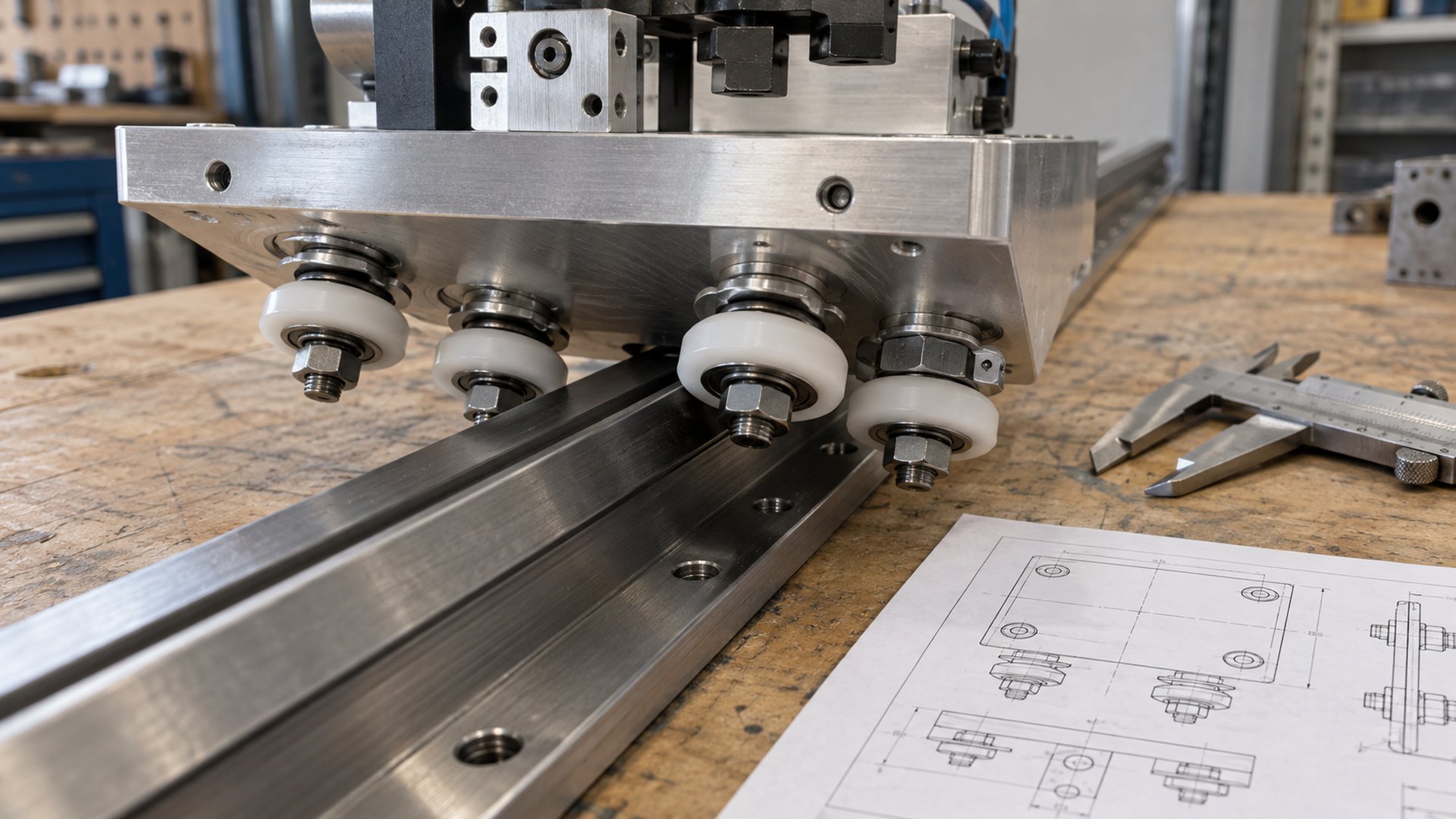 A functional carriage drawing should show the rail contacts, fixed and adjustable wheel positions, wheel spacing and fastener stack.
A common V-guide carriage uses four wheels, with two wheel positions separated along the direction of travel on each side of the rail. The separation between front and rear contact groups helps resist yaw and pitch. Opposing contact across the rail controls lateral movement and roll.
In many adjustable designs, two wheels use concentric studs to establish a fixed datum. The opposing wheels use eccentric studs or bushings. Rotating an eccentric changes the wheel center position by a small amount, allowing the assembler to remove clearance against the rail.
This arrangement is preferable to making every wheel independently adjustable. A fixed side creates a repeatable reference, while the adjustable side accommodates production variation. If every wheel position can float, the assembler may set the carriage skewed or create unequal load sharing.
The designer should identify:
- which contacts carry the dominant external load;
- which wheels establish the primary datum;
- which wheels provide opposing retention;
- where adjustment is located;
- how the setting is locked without shifting; and
- whether every wheel should be continuously loaded or some are safety/retention contacts.
More wheels can distribute load, but they also create a more statically indeterminate system. Rail straightness, plate flatness and wheel-position tolerances become more important because one wheel may unload while another carries excessive force.
Why Do Wheelbase and Rail Spacing Matter?
Greater separation between contact points usually improves resistance to moment loads, provided the carriage and rail remain stiff.
The payload rarely acts exactly through the center of the guide contacts. A cantilevered tool, motor, tray or robot axis creates moments.
- Front-to-rear wheelbase helps resist yaw and pitch.
- Vertical or cross-rail separation helps resist roll.
- Two separated rails can provide a wider support footprint than one compact rail.
- Two carriages spaced along one rail can resist moment better than one short carriage, if the rail and mounting surface support them correctly.
For the same external moment, increasing the effective contact spacing can reduce the reaction force required at each contact. However, a wider footprint does not automatically improve accuracy. A flexible carriage plate can twist between the wheels, and two rails mounted out of parallel can force the carriages against each other.
I normally draw the load line and calculate forces at each guide contact or carriage block. Total payload divided by wheel count is rarely sufficient. Acceleration, emergency stops, cable-chain pull, drive offset and process force can shift the reactions substantially.
Thomson’s article on selecting and applying rolling-element linear guides explains how bearing arrangement, mounting accuracy and preload affect deflection and guide performance. The article addresses several linear-bearing types, but the system principle applies here: support geometry and load direction must be considered together.
What Does Preload Do in a Roller Guide System?
Preload removes free play and increases initial stiffness, but too much preload raises friction, bearing load and wear.
Without preload, manufacturing clearance may let the carriage rock as the external force reverses. A small controlled interference at opposing wheel contacts keeps the wheels engaged and makes the carriage response more repeatable.
Preload can be introduced by:
- rotating eccentric wheel studs or bushings;
- adjusting a split or flexible carriage plate;
- selecting oversize rolling elements in a profile-rail block;
- moving one rail relative to another; or
- using springs where compliance is intentional.
HepcoMotion’s DualVee technical guide describes a common approach: concentric wheels establish position and eccentric wheels remove free play. It also warns that excessive preload can create undue stress and premature failure.
I do not approve preload from a vague instruction such as “tighten until there is no movement.” A production method should define a measurable condition, which may include breakaway force, running force, wheel rotation check, eccentric orientation or a dedicated setting fixture.
Preload cannot repair:
- a bent rail;
- a twisted machine frame;
- a carriage plate that deflects under payload;
- large wheel runout;
- incorrect groove-to-rail geometry; or
- two rails mounted out of parallel.
Increasing preload in these situations can hide looseness at one location while creating binding elsewhere. The carriage must be checked through its complete stroke, not only at the assembly position.
How Do the Wheel Profile and Rail Geometry Work Together?
The profile establishes where the wheel contacts the rail and which force directions the system can resist.
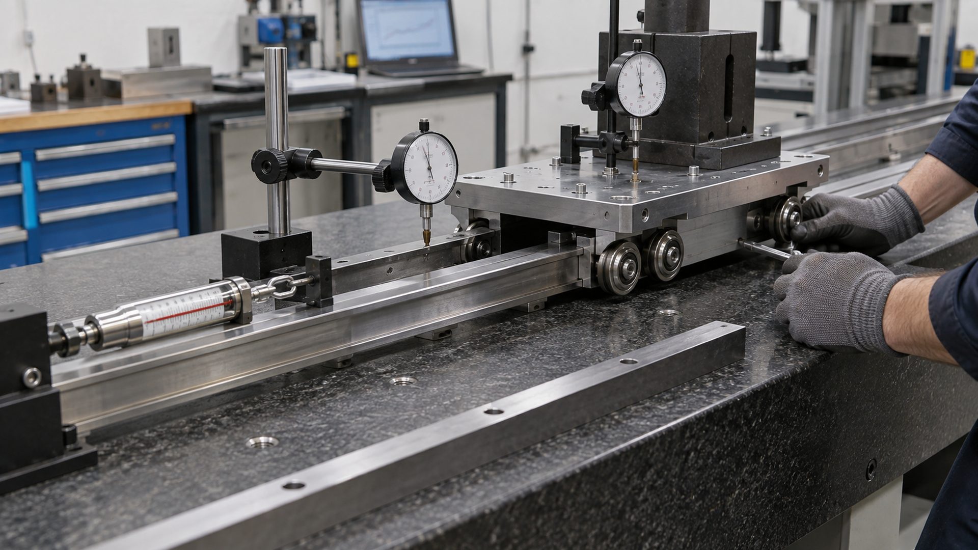 HUNE V-groove bearing wheels combine an engineering-plastic running profile with an internal ball bearing. The matching rail section and carriage layout still determine system guidance.
A V-groove wheel normally contacts two angled rail flanks. Those contacts can react forces in more than one direction and help locate the wheel laterally. A round or U-groove profile fits a different rail geometry. A flat wheel usually supports load normal to its face and needs another feature for side guidance.
Our article explaining why guide wheels use grooved profiles covers the contact geometry in more detail. The key point for a carriage is that every constrained direction needs a clear reaction path.
The wheel and rail drawing should define:
- included groove and rail angles;
- flank contact position;
- root and tip clearance;
- corner radii and edge condition;
- effective running diameter;
- rail straightness and surface finish;
- wheel material and hardness; and
- allowable wear before guidance becomes unacceptable.
If the V-wheel bottoms in the rail root, the intended flank contacts may not develop. If the rail edge is too sharp, it can concentrate stress or cut a polymer tread. If only one flank contacts because of angle mismatch, the system may show noise, high pressure and unstable tracking.
HUNE’s V-groove roller wheels with bearings illustrate one configurable wheel architecture for V tracks and angle rails. A product-page diameter or bearing number is not enough to approve a carriage; the rail, load, adjustment and mounting must be reviewed.
How Do Bearings Affect Straightness and Running Quality?
Bearings control wheel rotation and internal movement, but they cannot make an inaccurate wheel mount or rail straight.
Inside a guide wheel, the bearing transfers contact force from the outer wheel through its rolling elements to the axle or stud. Bearing clearance, fits, seals, lubrication and ring support influence radial movement and running torque.
Potential error sources include:
- bearing internal clearance;
- bearing-seat variation inside the wheel;
- wheel tread runout relative to the bearing bore;
- stud diameter and shoulder squareness;
- spacer or washer contact with the rotating ring;
- excessive inner-ring clamping distortion;
- bracket-hole position; and
- bearing contamination or corrosion.
Our guide to bearing clearance in OEM rollers explains why installed clearance can differ from unmounted bearing clearance. For a preloaded wheel carriage, distinguish the ball bearing’s internal clearance from the external preload between wheel and rail. They are related through deflection and fit but are not the same setting.
A higher-precision bearing may reduce one part of the error budget, yet finished carriage accuracy can still be limited by the molded wheel, stud, carriage plate and rail. I prefer to allocate an error budget across the complete assembly instead of specifying the highest bearing class by default.
For background on the component structure, see what a bearing roller is. The complete roller normally includes more than the bearing designation: the running profile, axle, spacers, fastening and track interface all affect function.
How Do Rail and Frame Accuracy Affect the Carriage Path?
The guide can only follow the geometry presented by its rail and mounting structure.
Rail straightness from the supplier does not guarantee installed straightness. Fastening a rail to an uneven extrusion, welded frame or distorted plate can bend it. Bolt tightening sequence and local debris can introduce additional error.
Important mounting relationships include:
- flatness and straightness of the rail support;
- rail position relative to the machine datum;
- parallelism where two rails are used;
- joint alignment for segmented rails;
- bolt-hole clearance and locating edge design;
- frame deflection under payload and acceleration; and
- thermal growth between rail, frame and carriage.
Thomson’s guidance on getting service life from profile rail notes that mounting-surface preparation and moment loading affect guide performance and durability. Although profile-rail blocks differ from open V-wheel systems, the mounting lesson is the same: precision components do not cancel errors in the structure supporting them.
For a dual-rail axis, one rail is normally treated as the master datum. The second rail needs a mounting strategy that achieves parallelism without forcing the carriages into internal stress. The exact method depends on rail type and equipment accuracy.
How Does the Drive System Influence Straight Travel?
A drive force applied away from the guide’s center of resistance creates a moment that the roller contacts must absorb.
A belt attached high above the carriage can create pitch. A belt attached to one side can create yaw. A screw nut mounted out of alignment can force the carriage laterally through its full stroke. A cable chain can add a changing side force as it bends.
The drive layout should therefore be checked for:
- force line relative to carriage guide contacts;
- belt or screw alignment;
- drive stiffness and backlash;
- acceleration and emergency-stop force;
- motor-cable and hose forces;
- end-stop impact; and
- coupling compliance.
Drive force should pass as close as practical to the center of guide resistance when straightness and low friction matter. Where that is impossible, include the resulting moment in the wheel-load calculation.
Two drive points can rack a wide carriage if they are not synchronized. One central drive can also twist a wide flexible plate. The carriage structure, rail spacing and control strategy must be evaluated together.
How Do Dust, Debris and Lubrication Change Performance?
Open roller guides can tolerate some contamination, but debris at the wheel-track contact changes height, preload and surface stress.
A chip on the rail can lift a wheel, tilt the carriage and create an impact load. Fine abrasive dust can wear both wheel and rail. Sticky residue can raise running force and create periodic error.
Possible controls include:
- track wipers or scrapers;
- covers and shields;
- rail orientation that discourages debris retention;
- sealed or shielded wheel bearings;
- suitable track lubrication where specified;
- corrosion-resistant bearing, axle and rail materials; and
- accessible cleaning paths.
Lubrication needs to be separated into bearing lubrication and wheel-to-track lubrication. A sealed bearing may contain its own grease while the external rail contact follows a different recommendation. A dry polymer wheel and an all-steel V guide may require different treatment.
HepcoMotion’s UtiliTrak catalogue discusses eccentric adjustment, system loading and external guideway lubrication for its products. Those instructions are product-specific, but they illustrate why an OEM should not assume that a “sealed wheel” makes the whole guide maintenance-free.
Which Functional Dimensions Should the OEM Drawing Control?
Control the dimensions that locate the wheel contacts and the carriage path, not only wheel diameter and bearing bore.
For each guide wheel, define or confirm:
- finished running diameter;
- groove profile and contact angle;
- tread runout relative to the bearing bore;
- bearing designation and protection type;
- hub fit and retention;
- stud or axle diameter, shoulder and thread;
- spacer and washer stack; and
- wheel material, hardness or grade where functional.
For the carriage assembly, define:
- fixed and eccentric wheel positions;
- wheelbase and opposing contact spacing;
- hole position relative to carriage datums;
- eccentric adjustment range and locking method;
- plate flatness and stiffness requirement;
- rail section and mounting datum;
- allowable lateral, vertical and angular error; and
- target breakaway or running force where useful.
For the machine structure, define:
- rail-support straightness and flatness;
- master datum and locating edge;
- parallelism between rails;
- maximum joint step or gap;
- bolt sequence or mounting procedure if critical; and
- inspection method over the full travel.
HUNE’s roller materials and process overview can help buyers compare POM, nylon, polyurethane, bearing protection and manufacturing routes before finalizing a custom wheel drawing.
How Should an OEM Validate a Roller-Guided Carriage?
Measure straightness, angular motion, running force and wheel loading across the entire stroke with the real payload.
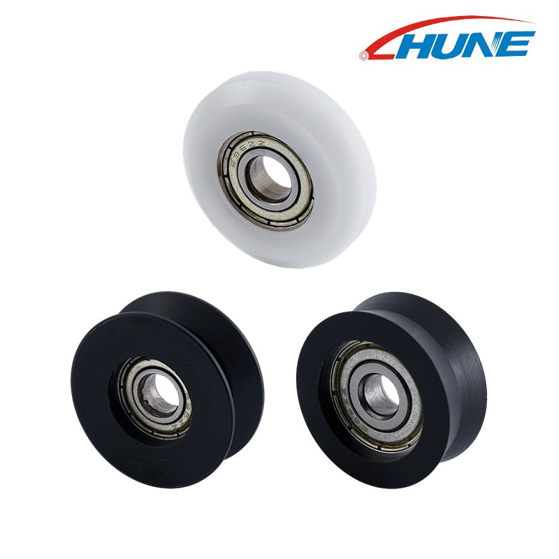 Carriage validation should measure the mounted system on its actual rail and structural datum, not only inspect individual wheels.
A practical validation plan can include:
- breakaway and steady running force over the complete travel;
- lateral and vertical deviation against a reference datum;
- pitch, yaw and roll at the functional tool point;
- carriage play under reversing side and moment loads;
- wheel rotation and contact through the full stroke;
- temperature and noise after the defined duty cycle;
- drive current or motor torque during acceleration;
- performance with the maximum payload and cable-chain position;
- debris, dust, humidity or wash exposure as applicable;
- tread, rail, bearing and stud wear after cycling; and
- retention of eccentric adjustment and fastener torque.
Measure the functional point, not only the carriage plate. A small angular error can create a larger lateral error at a tall tool, camera or dispensing head.
Acceptance criteria should distinguish repeatability from absolute straightness. A carriage that follows the same curved rail path repeatedly may have good repeatability but poor straightness relative to the machine datum. Both can matter, depending on the process.
What Information Should a Buyer Send the Roller Supplier?
A supplier needs the rail, carriage, load and adjustment information—not only a wheel photograph.
Send:
- machine function and carriage position;
- rail cross-section, material, hardness and surface finish;
- complete carriage drawing or 3D model;
- wheel count, layout and fixed/eccentric positions;
- normal and maximum payload;
- radial, axial and moment loads, including drive and cable forces;
- travel length, speed, acceleration and cycles;
- straightness, repeatability, play and running-force targets;
- environment, contamination, temperature and cleaning method;
- bearing, wheel and axle material preferences;
- required adjustment and locking method;
- prototype quantity, annual volume and tooling expectations; and
- current samples and failure evidence for replacement projects.
If exact wheel loads are unavailable, provide payload center of gravity, wheel spacing, rail orientation and drive-force location. These allow the system reactions to be estimated instead of dividing total mass equally across all wheels.
HUNE manufactures custom plastic-coated bearing wheels, V-groove rollers, axles, spacers and metal brackets for OEM guiding mechanisms. We can review the wheel and mating rail as one assembly and develop samples through the HUNE OEM process. To discuss a machine-carriage project, send HUNE the carriage, rail and duty information.
Frequently Asked Questions
Do more guide wheels make a machine carriage straighter?
Not automatically. Additional wheels can distribute load, but they also increase sensitivity to rail straightness, mounting position and preload. A well-spaced four-wheel arrangement can outperform a larger wheel count that is poorly aligned or unevenly loaded.
Should every guide wheel be preloaded against the rail?
That depends on the architecture. Many V-wheel carriages use fixed datum wheels and opposing adjustable wheels with controlled preload. Safety or retention wheels may use clearance instead of continuous load. Follow the approved load path and manufacturer method.
Can higher-precision bearings correct a carriage that wobbles?
Only if bearing error is the controlling cause. Wobble can also come from tread runout, loose studs, insufficient external preload, a flexible plate, worn rail or poor contact geometry. Inspect the complete wheel–stud–plate–rail stack.
What is the difference between straightness and repeatability?
Straightness measures deviation from a defined straight datum over travel. Repeatability measures how closely the carriage returns to the same path or position. A carriage can repeat a slightly curved path, so the OEM should specify both when the process requires them.
Practical Engineering Recommendation
Design the guide as a geometric constraint and structural load path before choosing an individual roller.
Place wheel contacts far enough apart to resist the real moments, establish a fixed datum, add only enough preload to remove functional play, and mount the rail on a structure that can preserve its geometry. Then validate running force, straightness and angular error across the full stroke with payload and drive forces applied. A correctly selected bearing wheel supports smooth motion, but the carriage stays straight only when the wheel, axle, adjustment, plate, rail and machine frame work together.


