

3D printing turns a digital model into a physical object by adding or solidifying material in successive layers. Software prepares the geometry for a chosen machine, which deposits plastic, cures resin or fuses powder to form the part. In a filament printer, coordinated material feed, heating and mechanical motion place each bead of plastic along a programmed path.
That answers how 3D printing works in principle. The engineering question is how reliably the machine can repeat the process. A correct model alone cannot guarantee that the finished part will have the intended dimensions, surface or strength.
This guide explains the main stages, compares common printing methods, and examines the role of bearing guide wheels in compatible FDM printers.
What Makes 3D Printing Different from Machining or Moulding?
3D printing builds geometry directly from digital instructions, usually without a dedicated mould.
A CNC machine removes material from stock. Injection moulding fills a shaped cavity. Additive manufacturing creates the object through controlled material placement or selective solidification. The U.S. Department of Energy's explanation of 3D printing describes this basic distinction and the progression from a digital design to a physical build.
This gives engineers another way to make prototypes, fixtures and production parts. It can be useful when geometry changes frequently or when internal features would be difficult to manufacture conventionally.
However, removing the need for a mould does not remove manufacturing constraints. Build orientation, supports, material behaviour, machine capability and finishing still affect the result. I would choose the process around the part's functional requirements and expected quantity.
How Does 3D Printing Work Step by Step?
The practical workflow connects design, process preparation, printing and inspection.
1. Create or obtain a digital model
The starting point is a three-dimensional description of the part. It may come from CAD software, a prepared model library or a scan that has been processed into suitable geometry.
Before printing, check scale, wall thickness and the features that must fit other components. A mounting hole, bearing seat or mating face needs deliberate design; simply making an object look correct on screen is insufficient.
2. Prepare the model in a slicer
A slicer converts the model into layer information and machine instructions. For many desktop filament printers, the output is G-code or a supported variant.
The operator selects the machine, material, build orientation and print settings. The software then plans features such as outer walls, internal infill and temporary supports. Preview the layers before printing to check that the intended geometry can actually be built. The PrusaSlicer preparation guide illustrates these steps for filament printing.
3. Prepare the machine and material
Load the appropriate feedstock and use the printer's required setup procedure. For FDM equipment, this commonly includes checking the build surface, nozzle condition, material profile and nozzle-to-bed relationship.
The motion system also needs to be stable. A loose carriage or binding guide changes the physical position of the nozzle even when the software instructions are correct.
4. Form successive layers
The printer follows the prepared build instructions. In FDM, it coordinates movement with plastic extrusion. In other processes, the machine may expose resin to light or apply energy to selected regions of a powder layer.
The relative position of the growing part and the forming mechanism advances as the build proceeds. The exact motion depends on the machine; the bed does not move in the same way on every printer.
5. Finish and inspect the part
After the build, follow the process-specific removal and finishing procedure. FDM parts may need support removal or secondary machining. Resin parts typically need cleaning and the specified post-curing. Powder-based parts require powder removal and may need additional thermal or mechanical treatment.
Inspect the features that determine whether the part works. A clean-looking surface does not confirm a correct bearing fit or adequate strength.
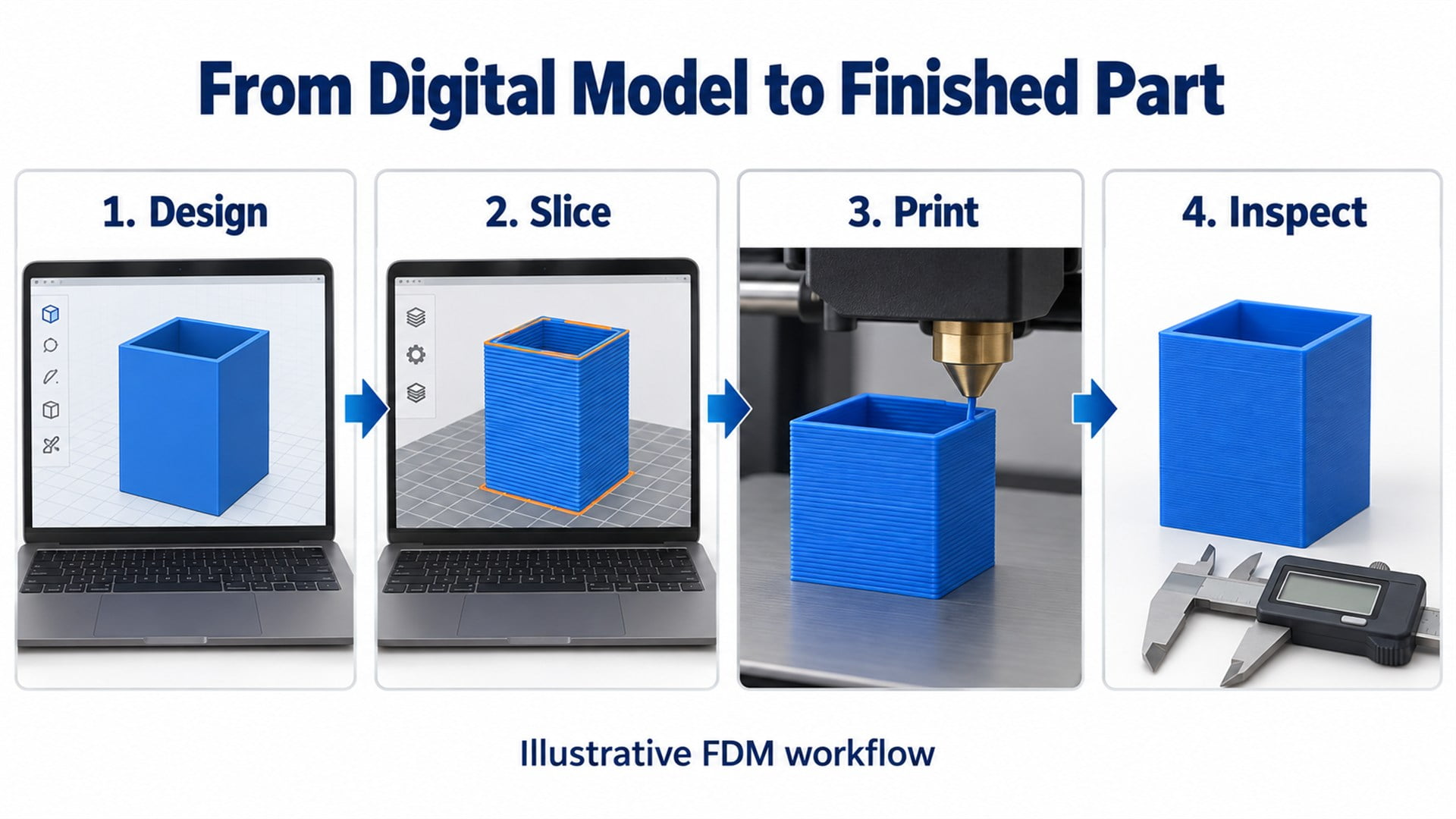 The same design moves through several manufacturing stages. Printing is one stage in the complete workflow.
How Does a Filament 3D Printer Form a Layer?
An FDM printer coordinates polymer flow with nozzle movement to create connected lines of material.
FDM and FFF are terms commonly used for filament-based material extrusion. NIST's material extrusion overview identifies this as a layer-building process used in both personal and commercial printing.
Drive gears grip the filament and feed it toward the hotend. The heated region brings the polymer to a condition where it can flow through the nozzle. The nozzle deposits a bead while moving relative to the build surface.
Within a layer, those beads form boundaries and internal paths. Subsequent layers build on the material already deposited. The hotend, material feed and travel speed must work together: commanding more movement without sufficient flow does not create a complete line.
The cold-side filament path must also remain controlled. The extruder's job is to meter material, while the hotend's job is to heat it. Treating these as separate functions helps explain why a feed problem and a temperature problem can produce similar-looking defects.
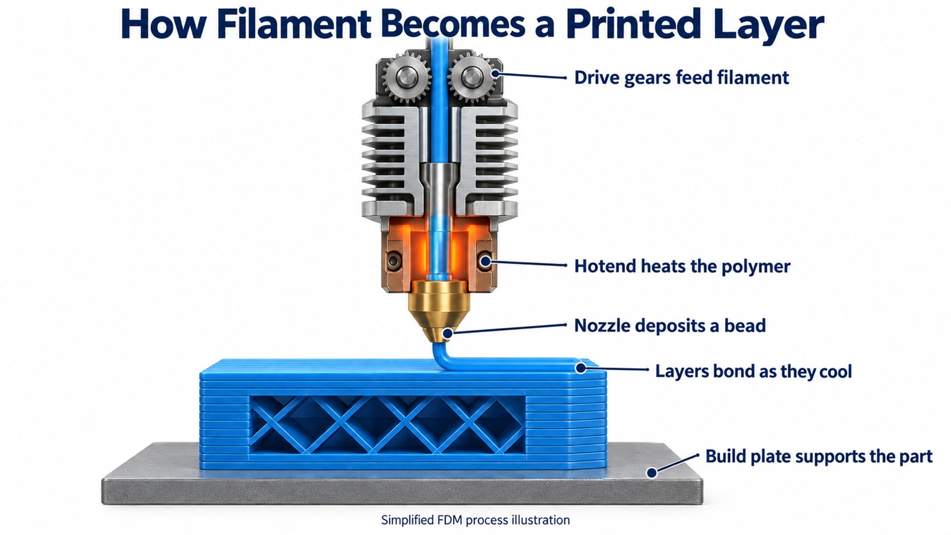
Material feed, heat and motion must stay coordinated while each bead is deposited.
Why do walls, infill and supports look different?
Walls define the part's boundary. Infill is an internal structure that can support upper surfaces and contribute to mechanical behaviour. Temporary supports help build features that cannot otherwise be formed successfully in the chosen orientation.
These features have different purposes. A higher infill percentage does not automatically correct a thin mounting wall or a poorly oriented load-bearing feature. Supports also need a removal plan where access is limited.
Do All 3D Printers Melt Plastic Filament?
No. FDM is one process family within a much broader group of additive manufacturing technologies.
The distinctions below follow the process families in NIST's additive manufacturing technology overview.
| Process | How the shape forms | What changes in an engineering review |
|---|---|---|
| Material extrusion, including filament FDM/FFF | A nozzle deposits material along a planned path | Feed consistency, layer bonding, nozzle access and motion repeatability |
| Vat photopolymerization, including SLA and DLP | Light selectively cures liquid photopolymer | Exposure, support placement, resin handling and post-curing |
| Powder bed fusion, including SLS and metal laser systems | Thermal energy selectively fuses regions of a powder bed | Powder handling, thermal history, support needs and finishing |
| Binder jetting | A liquid binder joins selected regions of powder | Fragile intermediate parts and subsequent processing; metals commonly require sintering |
This is a comparison of selected processes, not an exhaustive list.
For component buyers, the distinction matters. A bearing roller suited to an exposed aluminium-extrusion carriage should not automatically be specified for a hot chamber, a resin mechanism or a powder-handling assembly.
Which Components Control an FDM Printer's Motion?
The drive creates movement; the guide system constrains where that movement occurs.
Motors act through belts, drive pulleys, leadscrews or other transmissions. Bearings, guide wheels, shafts or linear rails support the moving assembly. The frame and carriage plates hold these components in their intended relationship.
The nozzle and build platform need controlled relative motion in three dimensions. Different printer layouts divide that movement differently between the tool head, gantry and bed.
A belt-driven carriage, for example, needs more than a motor and belt. The belt attachment must transmit force, the guide must resist unwanted displacement, and the carriage must remain sufficiently rigid under acceleration.
I first separate two questions: can the drive reach the commanded position, and can the guide hold the required alignment during that move? Increasing motor capability does not automatically solve carriage play.
Where Do Bearing Guide Wheels Fit into a 3D Printer?
In wheel-guided designs, bearing rollers let the carriage travel along a matching profile while supporting and constraining it.
A typical assembly includes a plastic wheel, one or more bearings, an axle or mounting bolt, spacers, a carriage plate and an aluminium guide profile. Several wheels work together to control the carriage.
The plastic running surface contacts the rail. The bearing allows the wheel to rotate around its axle. The mounting hardware locates the assembly, and the carriage plate connects it to the moving load.
HUNE's V-slot guide wheel with a 625 bearing for 3D printers is an example of this construction. It should be evaluated against the actual extrusion and mounting arrangement before selection.
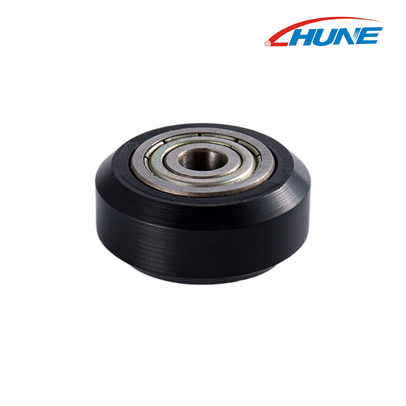
The wheel, bearing and mounting interface each contribute to the behaviour of the installed guide assembly.
Why does mating geometry matter?
Two wheels with similar outside diameters can contact a rail differently. The running profile, bearing location and assembled width determine where the load acts and how the carriage sits.
Too little contact can allow movement as forces reverse. Excessive preload can increase drag and deform the plastic running surface. A mismatched profile may contact an edge instead of the intended running faces.
The relevant comparison is therefore the installed wheel-to-rail interface. Our guide to specifying rollers for aluminium-extrusion motion systems explains the dimensions and contact conditions involved.
These guide wheels support motion; they do not feed filament. On a conventional belt-driven axis, the freely rotating guide wheel also does not set the motor-to-travel ratio.
What Determines the Accuracy and Strength of a Printed Part?
Printed quality depends on geometry, motion, material delivery and the part's thermal history together.
A smaller nominal layer height can improve the appearance of some surfaces, but it is not a general statement of dimensional accuracy. The finished part also reflects toolpath planning, nozzle behaviour, cooling, shrinkage and mechanical alignment.
For a wheel-guided machine, uneven wheel rotation or carriage play can disturb nozzle position. For extrusion, inconsistent delivery can change deposited line width. These effects can overlap, so a visible defect should not be assigned to one component without checking the system.
Strength deserves a separate assessment. Filament-printed parts contain interfaces between deposited paths and layers. NIST research on interlayer weld formation examines how thermal history and polymer behaviour influence bonding.
I would review build orientation against the service load and test the actual material-process combination. A generic filament name or attractive sample cannot establish a production part's allowable load.
What Should OEM Buyers Specify for Printer Guide Rollers?
Define the carriage interface and validation method before comparing unit prices.
A supplier needs to understand where the wheel runs, how it is mounted and what the assembly must support. “A wheel for a 3D printer” leaves too many functional decisions unresolved.
Send the supplier:
- A wheel drawing and the mating rail section, with revision numbers.
- The required running profile, assembly width and bearing-seat geometry.
- Bearing specification, axle or bolt details, spacers and carriage layout.
- Moving load, acceleration, speed, travel and duty cycle.
- Expected temperature, contamination and relevant material requirements.
- Functional tolerances, inspection datums, sample quantity and expected demand.
Prioritise the surfaces that affect motion. For example, specify relevant running-surface variation relative to an agreed bearing or assembly datum. A tight cosmetic dimension elsewhere may add cost without improving guidance.
Material and production route also require context. POM is a material family, not a complete grade specification. A printed shape check does not demonstrate the performance of a machined or moulded production roller.
When evaluating machining versus injection moulding for POM rollers, consider design maturity, tooling investment and repeat demand. Validate production-intent samples with the actual rail, mounting stack and carriage load.
The broader HUNE range of sliding rollers with bearings provides construction options to review against those requirements.
Frequently Asked Questions
How long does 3D printing take?
Build time depends on part size, orientation, material, layer settings, supports and the machine's process limits. For FDM, a slicer estimate is a useful starting point, but setup, cooling, support removal and inspection also contribute to delivery time. Compare the complete manufacturing cycle when deciding whether a process suits a production requirement.
Can a 3D printer make a fully solid object?
Yes, suitable processes can make nominally solid parts. In filament printing, an internal fill setting does not guarantee a void-free material structure. Deposited lines and layer interfaces can still influence density and strength. Specify the required function and verification method rather than assuming that a “solid” slicer setting establishes a particular mechanical property.
Can I 3D print a replacement guide wheel?
A printed wheel may help check space, overall shape or an early assembly concept. A working replacement also needs suitable running surfaces, bearing retention, dimensional stability and resistance to wear under the intended load. Validate those conditions before service. A geometry prototype should not be treated as proof that the production material and process are interchangeable.
Do all FDM printers use plastic bearing wheels?
No. FDM printers can use wheel-guided extrusion, linear rails, round shafts with bearings, or other arrangements. The appropriate guide depends on the machine design, operating environment and motion requirements. Confirm the installed architecture before selecting a roller; a product suitable for a V-slot carriage is not a universal substitute for other guide systems.
Discuss Bearing Rollers for Your Printer Project
HUNE manufactures sliding rollers with bearings and custom hardware components for OEM applications. For a printer using compatible wheel-guided motion, the useful starting point is a review of the complete carriage assembly.
Send HUNE your roller drawing and application requirements, including the mating rail, bearing arrangement, mounting details, load conditions and expected quantity. Agree on the functional dimensions and an installed sample test before approving the roller for production.


