

In a belt conveyor system, idler rollers support the belt and the material it carries while allowing the belt to move with low rolling resistance. Carrying idlers support the loaded upper run; return idlers support the unloaded return run. Some idler sets also shape the belt into a trough, support loading impact, or help manage tracking. Idlers do not normally drive the belt—the drive pulley does. The term can also describe a non-driven roller in other equipment, so engineers should state the duty clearly. An idler is part of a complete assembly that includes its shell, shaft, bearings, seals, mounting and frame. Its selection depends on the belt, load, speed, spacing and environment, not on the bearing alone.
What Is an Idler Roller in a Conveyor?
An idler roller turns freely as the moving belt passes over it; it supports and guides the belt but is not the conveyor’s primary drive.
In a conventional belt conveyor, the drive pulley transfers motor torque to the belt. Idlers support the belt along the route so it does not sag excessively under its own weight and the conveyed material. The idler rolls rotate as the belt moves across them.
The word “idler” is sometimes used loosely for any unpowered roller. In bulk-material belt conveyors, it often refers to one roll or a set of rolls mounted in a frame beneath the belt. CEMA’s Standard 502-2022 description covers troughing, return and picking idlers for bulk-material conveyors. The support arrangement varies with the carrying or return side and the conveyor duty.
An idler assembly may include several functional parts:
| Part | Function |
|---|---|
| Roll shell | Provides the rotating surface that contacts the belt |
| Shaft or axle | Locates the roll in its support structure |
| Bearings | Allow the shell to rotate around the shaft |
| Seals | Help limit entry of dust, moisture or other contaminants |
| Frame or brackets | Hold one or more rolls in the required position |
| Mounting interface | Connects the assembly to the conveyor structure |
The load path runs from the material through the belt, into the idler shell and bearings, then through the frame into the conveyor structure. If any part is mis-specified or misaligned, the result can be extra drag, uneven belt contact, noise, heat or accelerated wear.
What Does a Carrying Idler Do?
A carrying idler supports the loaded upper belt run between the loading and discharge areas.
A flat carrying idler uses one horizontal roll. A troughing idler uses a centre roll with angled wing rolls to form a shallow trough in the belt. The trough shape can help contain bulk material across the belt width. The choice depends on belt design, conveyed material, loading and the conveyor structure.
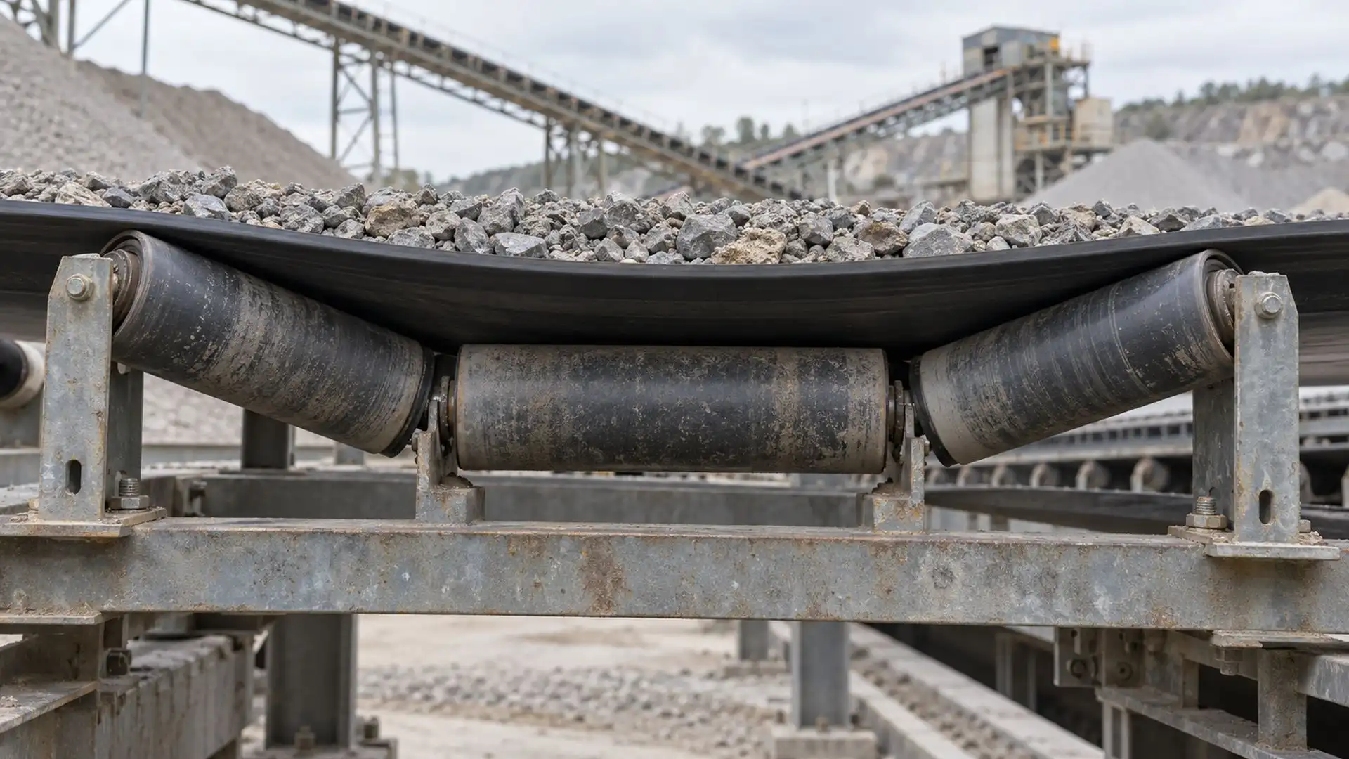 The centre and wing rolls support the belt as a set and establish its cross-sectional shape.
Idler spacing is a system dimension. If the span between supports is poorly matched to belt stiffness and load, the belt may sag or its contact with the rolls may become uneven. At loading points, the material can also strike the belt and support structure; that region may need a design intended to handle impact rather than a standard carrying set.
A carrying idler is not the only part that supports the belt. Transfer zones, loading chutes, skirtboards and impact beds can change the local support arrangement. The designer should consider the full path and loading condition, not simply count rolls along a straight section.
What Does a Return Idler Do?
A return idler supports the belt after it has discharged the material, as the belt travels back toward the loading end.
The return run is usually unloaded, but it still has to be supported along the conveyor. A return idler is commonly a single horizontal roll mounted beneath the conveyor stringers. Some systems use V-return arrangements or other designs to suit tracking and structure requirements.
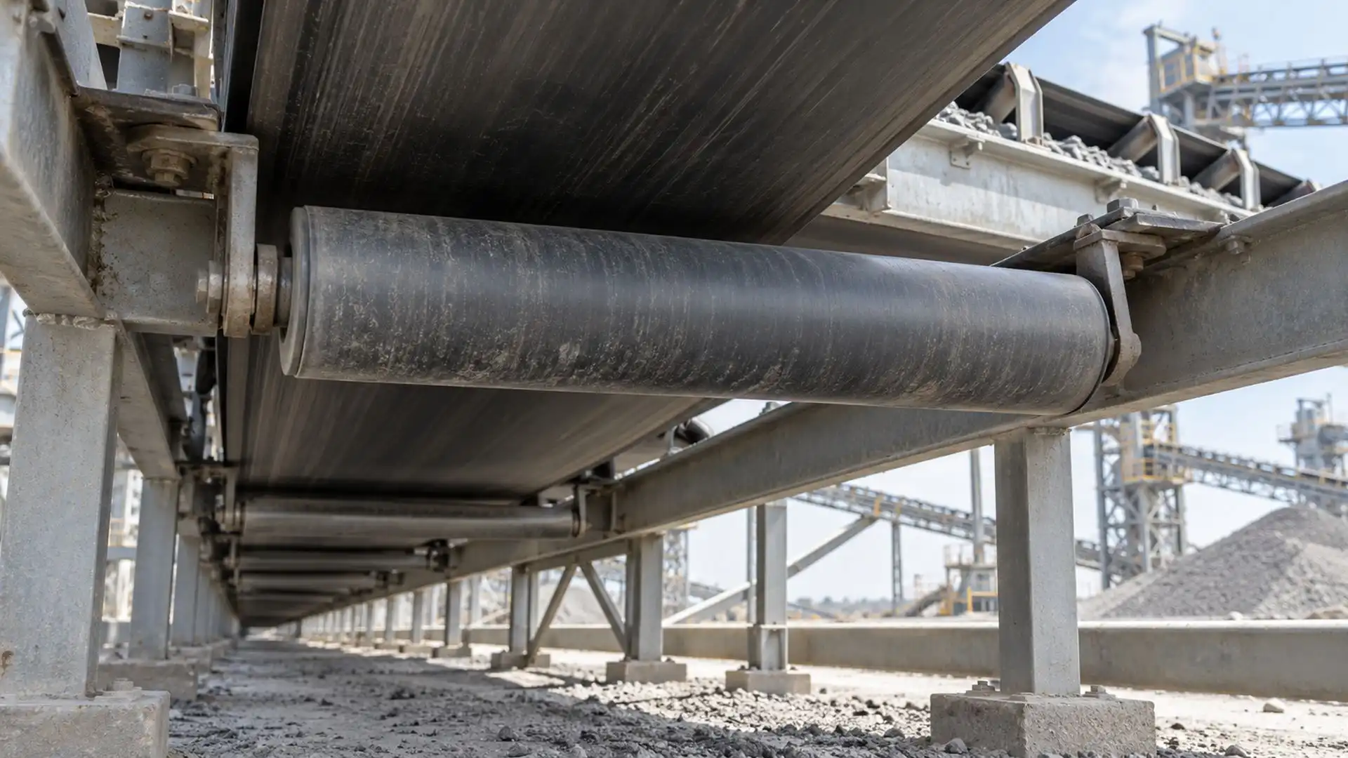 The return roll supports the lower belt run on its way back to the loading end.
Material carried back on the belt, dust and environmental exposure can affect return-side components. Return idlers therefore need to match the belt width, operating speed and surrounding conditions. The same assembly should not be assumed suitable for both the loaded carrying side and the return side without checking how each is loaded and mounted.
What Other Idler Types Are Used?
Different idler arrangements address different points in the belt path; their names describe the job and location, not interchangeable products.
| Idler type | Main role | Design point to confirm |
|---|---|---|
| Flat carrying idler | Supports a flat belt and load | Belt width, span and load distribution |
| Troughing idler | Supports and shapes the loaded belt | Trough angle, roll arrangement and material |
| Return idler | Supports the unloaded belt run | Return-side mounting and contamination |
| Impact idler or impact bed | Supports the belt at a loading zone | Drop conditions and impact-energy path |
| Training or self-aligning idler | Responds to belt mistracking through a pivoting or steering arrangement | Alignment method and correct operating conditions |
| Transition idler | Supports the belt as it changes between a flat and troughed profile | Location near a pulley and change in belt shape |
A training idler can assist belt tracking in a design intended for that purpose. It is not a substitute for sound conveyor geometry, proper loading or correction of a persistent alignment problem. Likewise, an impact idler is a support choice for a loading condition; it does not replace a complete review of the chute, belt and structure.
Martin Engineering’s technical guide to belt support with idlers describes carrying, return and other idler arrangements. The key engineering point is to select the assembly for its location and duty rather than using “idler roller” as if it identified one universal part.
How Is an Idler Roller Different from a Drive Pulley or Conveyor Roller?
An idler supports a moving belt without driving it; a drive pulley powers the belt, while a roller conveyor carries products directly on its rollers.
These terms refer to different roles:
| Component | What it contacts | Primary job |
|---|---|---|
| Conveyor idler | The underside or carrying surface of a belt | Support or shape the belt |
| Drive pulley | The belt at the drive point | Transfer torque and move the belt |
| Tail or bend pulley | The belt at a change of direction | Redirect the belt |
| Roller-conveyor roller | The conveyed box, tote or other unit load | Carry or advance the product |
| Compact guide roller | A belt edge, rail, cable, carrier or product edge | Limit lateral movement or guide a path |
Some systems use belt-driven live rollers or other hybrid layouts, so the assembly drawing should show which surface carries the product and which part applies drive. A loose catalogue name is not enough to establish the load path.
What Should Engineers Check When Selecting an Idler Assembly?
Select the complete assembly for belt contact, load, speed, mounting and environment.
I would confirm these system conditions before specifying a replacement or new idler:
- Belt width, profile, material and carrying or return position.
- Conveyed material, load distribution and loading-zone impact.
- Belt speed and the expected roll rotation speed.
- Idler spacing, trough angle and the adjacent support arrangement.
- Roll diameter, face length, shell material and surface condition.
- Shaft ends, bearing arrangement, seals and lubrication approach.
- Frame dimensions, mounting slot or hole geometry and alignment datum.
- Exposure to dust, moisture, temperature variation, chemicals or washdown.
- Required noise, runout, vibration and operating-life criteria.
The roll diameter and belt speed determine rotational speed together; the belt’s contact path and roll geometry matter when estimating that speed. Bearings then need to be selected for the loads, speed, fits and contamination protection of the complete roll. A bearing catalogue rating by itself does not establish the rating or service life of the assembled idler.
Pay attention to functional mating geometry. The roll face must be long enough for the specified belt contact; shaft ends must fit the frame; and the mounting arrangement must hold the rolls at the required angle and position. Runout and bearing fits can influence vibration and rolling resistance. These requirements should be set by the conveyor designer for the application rather than guessed from a generic idler description.
How Are Compact Guide Rollers Different from Conveyor Idlers?
A compact bearing wheel can guide a belt edge or moving part, but it is not automatically a belt-support idler for a conveyor’s main load.
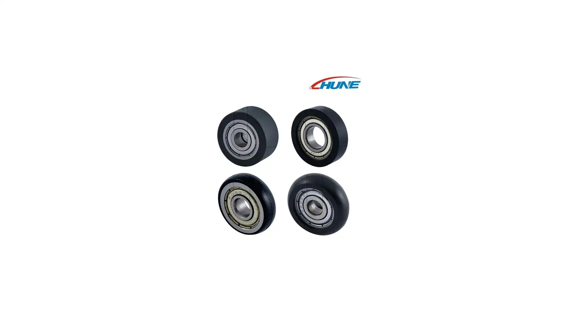 These HUNE wheels are compact plastic-coated bearing rollers. Their application depends on the mating surface and mounting; they are not bulk-conveyor carrying idlers.
A small plastic-coated bearing roller may contact a belt edge, help guide a carrier, or locate a moving fixture against a rail. That is a local guidance function. A belt-support idler normally spans a section of conveyor and carries belt load through its roll shell, bearings and frame. The two parts differ in size, mounting, load path and operating environment.
HUNE manufactures compact bearing rollers and plastic-coated guide wheels for equipment applications. For a conveyor guide, the mating profile and contact duty should be specified together; our guide to plastic-coated bearings for conveyor guide systems explains those considerations. Our overview of what a bearing roller is also distinguishes a bearing wheel from the complete mechanism around it. For machine carriage guidance, see how roller guide systems keep machine carriages moving straight.
Do not use a compact guide wheel as a substitute for a purpose-designed conveyor idler when the part is expected to support the main belt and material load. The equipment designer must define the complete assembly and validate it for its intended role.
What Information Should an OEM Send a Supplier?
A useful RFQ describes the conveyor position and duty as well as the part dimensions.
For a complete idler or roll assembly, provide:
- Conveyor and belt drawings, including the idler location.
- Belt width, profile, speed and carrying or return position.
- Material load and distribution, plus any loading or impact conditions.
- Required roll diameter, face length, shell material and finish.
- Shaft-end dimensions and mounting-frame geometry.
- Bearing and seal requirements, if already specified.
- Operating environment, duty cycle and expected order quantity.
- Critical runout, vibration, noise or other acceptance criteria.
- A sample, section drawing or clear photos of the current assembly, if available.
If the inquiry concerns a compact guide roller rather than a conveyor idler, send the mating rail or belt-edge geometry, contact direction, clearance, speed, expected force and mounting stack. HUNE’s OEM process begins with the drawing or sample and operating requirements so the supplier can review the actual application.
Frequently Asked Questions
Do idler rollers drive a conveyor belt?
Usually, no. In a conventional belt conveyor, the drive pulley transfers motor torque to the belt. Idler rollers support or shape the belt as it moves.
Are carrying idlers and return idlers the same?
They are both belt-support rollers, but they serve different runs. Carrying idlers support the loaded upper belt; return idlers support the belt after discharge on its way back.
What is a troughing idler?
A troughing idler is a set of rolls arranged with angled wing rolls and a centre roll to support the belt in a trough-shaped profile. The exact geometry is selected for the belt and conveyor duty.
Is an idler roller the same as a roller-conveyor roller?
No. A conveyor idler contacts and supports the belt. A roller-conveyor roller directly supports or advances the conveyed product. The product interface and load path differ.
Can a small bearing roller replace a conveyor idler?
Not automatically. A compact bearing wheel may guide a belt edge or carrier, but a main belt-support idler needs a complete assembly designed for its belt width, load, speed and mounting.
Practical Recommendation for OEM Buyers
Specify idlers by location and function: carrying, return, impact, transition or tracking. Then define the belt, load, speed, mounting, bearing and environmental requirements for the complete assembly. Confirm the design with the conveyor manufacturer and validate it under representative operating conditions.
If your equipment uses compact guide rollers alongside a conveyor, send HUNE the drawing or sample, mating geometry, operating conditions and quantity through our contact page. We can assess the guide-wheel or plastic-coated bearing portion of the project; the conveyor designer should specify the main belt-support idler system.



[…] sliding as the product rounds the bend. On the straight infeed or return runs of a belt system, idler rollers support the belt; that support role is separate from the curve […]