

Sliding wardrobe doors usually stick because the rollers, track and door structure no longer share load along the intended path. The immediate resistance may come from a wheel rubbing a rail shoulder, a bearing that does not rotate freely, a track that has deflected, or a door panel that has twisted. Excess door weight can make each of these effects more severe, but weight alone is rarely the complete explanation.
For an OEM project, I would not diagnose the problem from the wheel alone. I would check the complete system: door panel, roller housing, bearing or bushing, axle, running profile, top guide, bottom track, cabinet frame and adjustment range. Smooth movement depends on compatible geometry and controlled clearances throughout that chain. This article explains which interfaces create sticking and what a furniture manufacturer should define before selecting or sourcing the hardware.
How Should a Sliding Wardrobe Door Move?
A wardrobe door moves smoothly when its weight follows a stable load path and its guides control lateral motion without adding excessive preload.
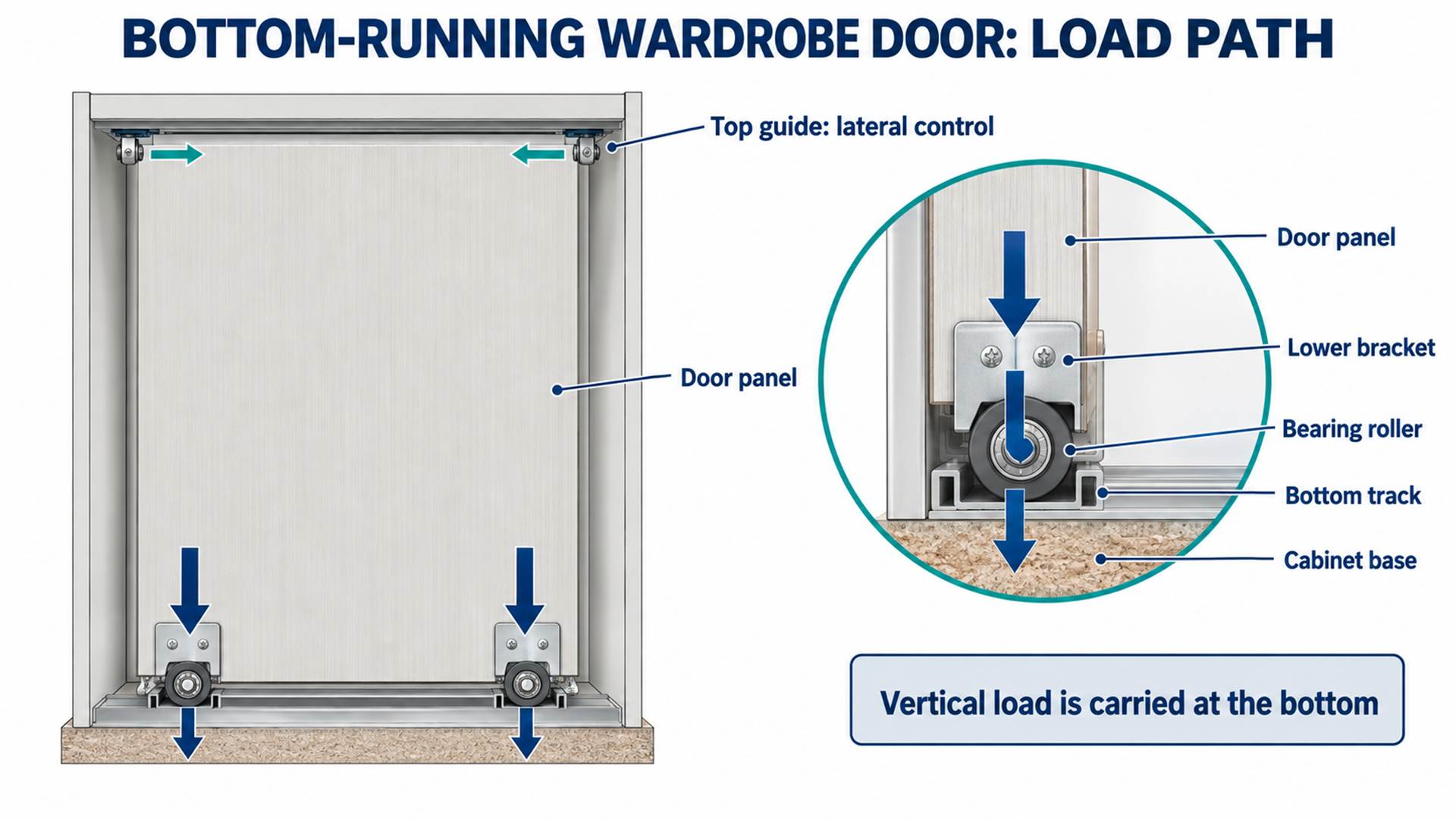 In a bottom-running system, the lower rollers carry the door weight while the upper guides control lateral position.
In a bottom-running system, the load path is typically:
Door panel → lower frame or bracket → roller housing → wheel → bearing or bushing → axle → bottom track → cabinet base.
The top guide normally controls the door laterally and helps prevent tipping or disengagement. It should guide the panel without carrying unintended vertical load. In a top-hung system, this arrangement is reversed: the upper carriers support the weight, while the lower guide controls lateral movement.
This distinction matters because a component can look like a “roller” while performing a very different job. A load-bearing wheel needs suitable bearing support, tread geometry and bracket stiffness. A positioning roller may only guide a light panel and can use a simpler structure. HUNE's bearing-free positioning roller for wardrobe systems is an example of a component intended for light-duty guidance rather than a universal door-support role.
The Element Designs sliding-door technical manual illustrates this division clearly in a bottom-glide system: two lower carriers support the door load, while two upper guides control the panel. The practical lesson is that a buyer must identify which hardware carries weight and which hardware only locates the door.
What Does “Sticking” Actually Mean in a Door System?
Different movement symptoms point to different interfaces, so the operating pattern is more useful than the word “stick.”
| Movement symptom | Likely system-level cause | Engineering question to check |
|---|---|---|
| High force from the first millimetre | Bearing drag, excessive guide preload or rubbing flange | Which parts remain in contact before the door gains speed? |
| Resistance at one position | Track joint, local track deformation, cabinet twist or panel bow | Does the symptom follow the door or remain at one rail location? |
| Repeating pulse as the wheel rotates | Tread runout, wheel flat spot, eccentric bearing seat or local wheel damage | Is resistance synchronized with wheel rotation? |
| Door moves easily in one direction only | Misalignment, asymmetric bracket deflection or soft-close interaction | Are the rollers square to the track in both directions? |
| Door becomes harder to move when loaded or after panel change | Inadequate roller capacity, housing deflection or poor load sharing | Did the centre of gravity or total door mass change? |
| Door rubs another panel or cabinet surface | Incorrect offset, panel warp, insufficient lateral clearance or guide error | Which datum controls the panel-to-panel gap? |
This table is a design diagnostic, not a substitute for inspection. Several causes can produce the same symptom, and more than one tolerance may be involved. I normally separate problems that remain at one track location from problems that move with the door. That first distinction quickly narrows the relevant components.
How Do Roller and Track Geometry Cause Sticking?
The wheel and rail must contact on the intended running surfaces while retaining enough side clearance for manufacturing and assembly variation.
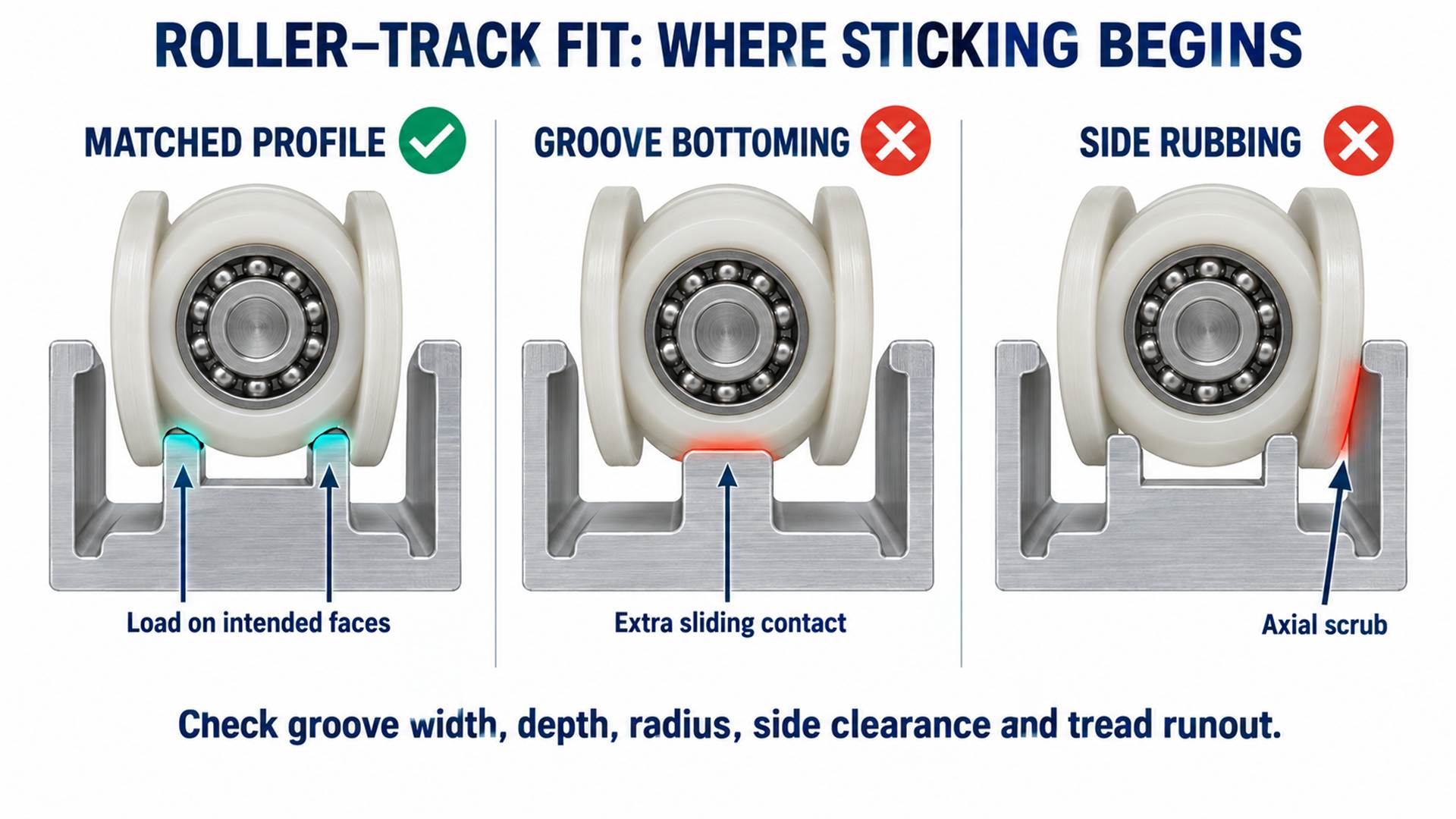 A matched profile carries load on the intended running surfaces; side rubbing or bottoming creates drag and unstable wear.
The nominal wheel diameter is only one dimension. The functional interface includes:
- the finished running diameter;
- wheel width and tread crown;
- groove width, depth, radius and included angle where applicable;
- flange diameter and side clearance;
- track crown, rib or channel profile;
- vertical clearance to the housing;
- axial position of the wheel relative to the bracket;
- radial runout of the tread relative to the bearing bore;
- track straightness, joint continuity and mounting support.
A grooved wheel should not bottom in the rail unless the system is specifically designed for that contact. If both groove faces clamp the rail, or if a flange continuously rubs a track wall, the wheel experiences sliding friction in addition to rolling resistance. A wheel that is too narrow may wander or contact an edge; one that is too wide may bind when the track width varies.
The same principle applies to flat wheels. The apparent contact surface may be wide, but load often concentrates over a smaller region because of wheel crown, track shape and elastic deformation. A bearing roller therefore has to be evaluated as a wheel, bearing, axle and mating track rather than as a bearing number wrapped in plastic.
I treat the wheel profile and track section as a matched pair. For a custom part, a supplier should receive the actual track cross-section or a controlled sample, not only the wheel outside diameter.
How Can the Roller Assembly Make a Door Feel Heavy?
A low-friction bearing helps, but wheel material, concentricity, clamping and housing stiffness determine whether that benefit reaches the door.
The internal bearing reduces rotational resistance between the wheel and axle. It cannot correct a wheel that rubs the housing, a bracket that bends under load, or a molded tread that is eccentric to the bearing.
Important roller-level causes include:
Bearing or bushing drag
A sealed bearing may have more starting torque than a shielded bearing because a contacting seal adds friction. A plain plastic bushing may be appropriate for light, slow guidance, but its performance depends on shaft finish, clearance, material and load. Selection should follow the duty and environment rather than the lowest unloaded hand-spin resistance.
The SKF rolling-bearing catalogue explains that lubrication is required to reduce friction, inhibit wear and protect bearing surfaces. In a compact sealed wardrobe roller, bearing lubricant and seal configuration are normally part of the bearing specification; they should be reviewed together with starting torque and contamination protection.
Incorrect ring clamping
If a fastener or spacer clamps both bearing rings, the rotating ring may not turn freely. The axle stack should locate the stationary ring while leaving the rotating ring and wheel clear of adjacent faces.
Tread runout
If the wheel's running surface is not concentric with the bearing bore, the door rises and falls slightly during each revolution. Under load, this can feel like repeated sticking. The drawing should define the bearing bore or bearing axis as a datum for tread runout where that relationship controls movement.
Wheel material and deformation
POM, nylon, polyurethane and other polymers offer different balances of stiffness, noise, wear, moisture response and molding behavior. A softer tread can reduce impact noise but may deform more under static load. A harder wheel may roll efficiently but transmit more track noise. The exact grade, wall thickness and geometry matter; the polymer name alone is not a complete specification.
For OEM quantities, HUNE's sliding rollers with bearings show several ways to combine a molded wheel and rolling bearing. When deciding between machining and molding for a new profile, the POM roller manufacturing comparison explains the volume, tooling and dimensional trade-offs.
How Does the Track Create Resistance?
The track must preserve the intended section and alignment after it is fixed to the furniture structure.
A correct roller cannot run smoothly on a rail that is locally crushed, twisted or unsupported. The relevant track characteristics include:
- cross-sectional profile at the wheel contact;
- straightness along the travel length;
- consistency through joints and end connections;
- support spacing and base stiffness;
- surface condition and coating build-up;
- mounting fastener position;
- allowance for thermal and material movement;
- resistance to contamination expected in service.
Thin track sections can change shape when fasteners are over-concentrated or when the cabinet base is not flat. A joint with a height step produces an impact that can be mistaken for a defective bearing. A track that bows sideways forces the guide and load rollers to steer continuously, adding scrub.
Track contamination is also an operating condition that the design must tolerate. Dust, textile fibres and small hard particles can interfere with small wheels more readily than with larger wheels. For OEM selection, the question is not merely whether the track can be cleaned; it is whether the profile, wheel diameter and protective housing are appropriate for the expected environment.
Why Does Door Weight Change Smoothness?
Door mass increases contact load, bracket deflection and sensitivity to unequal load sharing.
The total door mass includes the panel, frame, mirror or glass, handles, decorative inserts and attached hardware. Its centre of gravity also matters. A heavy surface layer mounted away from the roller plane can increase the moment applied to the brackets and guides.
With two load-bearing rollers, the door weight is not automatically divided equally. Differences in adjustment height, bracket position, track level and frame stiffness can shift more load onto one roller. The heavily loaded wheel may deform more, its housing may tilt, and its bearing may operate under unintended edge or axial loading.
The Hettich Sliding & Folding catalogue states system load capacity as permissible total door weight used with permitted door sizes. That is the correct level of thinking: roller capacity, door dimensions, fastening and furniture structure must be validated together.
I would not approve a roller solely because its individual component rating exceeds half the calculated door weight. The full assembly also sees dynamic effects at starts, stops, track joints and end stops. Any required design factor and test method should come from the system specification rather than an invented universal multiplier.
How Do Cabinet Squareness and Door-Panel Warp Affect Movement?
A sliding system can bind even when every hardware component meets its own drawing.
The upper and lower tracks need compatible datums. If the cabinet opening racks into a parallelogram, the distance and lateral relationship between those tracks change along the travel. The guides may preload the door at one end and loosen at the other.
The door panel itself can bow or twist. A bowed panel may contact another door, a vertical frame or the cabinet carcass. It can also move the roller brackets out of parallel. The hardware then spends part of its capacity correcting the panel rather than guiding straight motion.
Material construction influences this risk. EGGER's laminate processing instructions note that a flat, tension-free core is a prerequisite for a smooth surface and that certain core materials can present increased warping risk. For a wardrobe manufacturer, balanced panel construction, frame stiffness and hardware layout should be reviewed as one design.
Relevant assembly-level controls include:
- cabinet opening squareness;
- parallelism and spacing of the upper and lower track datums;
- door-panel flatness or permitted bow;
- roller bracket location relative to the panel edges;
- panel-to-panel overlap and clearance;
- adjustment range after all finishes are applied.
Can Guides, Anti-Jump Features and Soft-Close Units Cause Sticking?
Safety and motion-control features need defined clearance and engagement; uncontrolled preload can turn them into drag sources.
An anti-jump feature helps keep a roller engaged with the rail when the door is moved quickly or encounters a local irregularity. A top guide keeps a bottom-running panel upright. A soft-close unit captures the moving door and controls the final part of travel. Each feature is useful, but each introduces another interface.
Potential conflicts include:
- a guide adjusted tightly against both sides of its channel;
- an anti-jump clip that rubs continuously instead of engaging only when needed;
- a soft-close trigger located too high, low or laterally offset;
- a damper whose capture force is unsuitable for the door mass;
- insufficient space between the roller housing and the surrounding profile;
- an adjustment mechanism that shifts the wheel out of alignment as height changes.
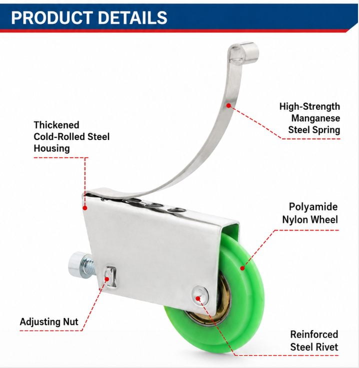 Existing HUNE media-library image showing a bottom roller assembly with wheel, housing, spring and adjustment feature.
HUNE's anti-jump wardrobe door bottom roller combines a bearing wheel, steel housing, spring structure and adjustment feature. For OEM integration, the wheel profile must match the rail, while the housing envelope and spring path must clear the door profile throughout adjustment and travel.
Which Functional Dimensions Matter Most?
Control the dimensions that determine rolling contact, load transfer and clearance before tightening cosmetic or non-contact features.
| Component | Functional dimensions or controls | Why they matter |
|---|---|---|
| Wheel | Running diameter, width, groove profile, tread runout | Establish rolling contact, door height and motion consistency |
| Bearing or bushing | Bore, outside diameter, width, fit and axial freedom | Control rotation around the axle and retention in the wheel |
| Axle and fastener stack | Diameter, shoulder length, spacer width, clamp faces | Locate the stationary member without locking the rotating member |
| Housing or bracket | Wheel centre position, mounting hole location, stiffness, adjustment travel | Transfer load and keep the wheel square to the track |
| Track | Contact profile, straightness, joint height, support datum | Maintain continuous rolling contact along the travel |
| Top guide | Guide width, lateral clearance, engagement depth | Control sway without adding excessive side preload |
| Door and cabinet | Panel flatness, track spacing, opening squareness, overlaps and gaps | Prevent rubbing and unequal loading at assembly level |
Not every surface needs the same tolerance. Tight limits on a hidden cosmetic edge do not improve motion if tread runout and track geometry remain uncontrolled. I first identify the contact surfaces and datums, then assign tolerances that can be measured by the chosen production and inspection method.
How Should an OEM Validate Smooth Door Movement?
Validation should progress from geometry to installed-system performance and then to repeat-production control.
A practical approval sequence is:
- Requirement review: Confirm door construction, dimensions, mass, centre of gravity, travel, duty, environment and target operating feel.
- Interface review: Compare the wheel profile with the actual track section and check the full housing envelope through its adjustment range.
- Geometry sample: Verify fit, clearance, track engagement and bracket location before committing to production tooling.
- Material and bearing confirmation: Approve the polymer grade, bearing or bushing, seals, lubricant specification where relevant, housing material and finish.
- Installed-door test: Evaluate starting force, movement through the full travel, load sharing, rubbing, noise, end-stop behavior and safety retention in the actual cabinet.
- Pilot production: Confirm that production variation in wheels, brackets, tracks and door panels still assembles within the intended adjustment window.
- Repeat-production inspection: Control the dimensions and checks that were shown to affect movement rather than inspecting every feature equally.
A free-spinning roller on a bench does not validate a wardrobe door system. The installed test is where track alignment, panel behavior and load sharing become visible.
What Should a Buyer Send to a Wardrobe Roller Supplier?
A useful inquiry defines the complete door system and the commercial stage of the project.
Send the supplier:
- A door and cabinet assembly drawing, including upper and lower tracks.
- Door width, height, thickness, finished mass and panel construction.
- Whether the system is bottom-running or top-hung.
- The roller's role: load carrying, guiding, anti-jump, positioning or damping interaction.
- Track cross-section, material, finish and a physical sample when available.
- Wheel running diameter, width, groove profile and required material or performance goals.
- Bearing or bushing requirement and axle/fastener stack.
- Housing envelope, mounting points and adjustment range.
- Expected duty, environment, contamination, noise and operating-force targets.
- Sample quantity, validation plan, annual volume and forecasted design life.
If a current door sticks, include the symptom pattern and identify whether it follows the door or stays at one track position. Photos, short videos and measured assembly conditions are more useful than asking for a wheel that “rolls more smoothly.”
FAQs
Why does a sliding wardrobe door stick only in one place?
Resistance at one fixed position usually points to the track or cabinet geometry: a joint step, local rail deformation, mounting distortion or changing distance between the top and bottom guides. If the resistance moves with the door, the roller, panel or bracket is more likely involved.
Can heavier wardrobe doors use the same rollers as lighter doors?
Only if the complete hardware system is approved for the finished door mass, dimensions and construction. A heavier panel changes wheel contact load, bracket deflection and dynamic forces. The roller, track, fasteners, guides and cabinet support must be evaluated together.
Is a ball-bearing roller always smoother than a plastic bushing roller?
No. A bearing can reduce axle friction, but seals, clamping, tread runout and wheel-to-track contact still affect movement. A simple bushing can suit light, slow guidance when its material, clearance and shaft are correctly matched.
What roller dimensions should match the wardrobe track?
The running diameter, wheel width and groove or tread profile must match the track's functional contact surfaces. Side clearance, engagement depth, flange position and housing clearance also matter. The safest sourcing package includes the controlled track cross-section or a physical sample.
Discuss Your Wardrobe Door Roller System with HUNE
The best sourcing decision starts with the door, track and load path, then selects the roller that fits those interfaces.
HUNE manufactures plastic-coated bearing rollers, wardrobe and closet door hardware, stamped housings and customized molded components for OEM customers. We can review the wheel profile, bearing or bushing, bracket, spring feature, axle stack and mating track as one assembly.
Send your door drawing, track section or sample, finished door mass, mounting space, operating conditions, target quantity and current movement symptom through the HUNE contact page. Our practical recommendation is to validate the complete installed system before freezing the roller drawing or approving repeat production.


