

A conveyor belt works as a continuous loop that travels around rotating pulleys. A motor turns the drive pulley; friction or a positive engagement transfers that motion to the belt. The belt carries products along its upper run, while rollers or a slider bed support it. At the far end, the belt turns around a tail pulley and returns underneath to the drive end. Tension, tracking and frame alignment keep the loop running in its intended path.
The system is more than a belt and motor. Drive and tail pulleys, carrying idlers, return rollers, take-up components, bearings, frame and controls each have a different job. Small plastic-coated bearing rollers may guide a belt edge or product, but they are not automatically the main load-carrying idlers. That distinction matters when engineers define the conveyor architecture or ask a supplier to quote a custom guide roller.
What Are the Main Parts of a Belt Conveyor?
A belt conveyor needs a moving loop, a drive, support, tension control and a structure that keeps those parts aligned.
| Component | Main function | What the designer checks |
|---|---|---|
| Conveyor belt | Carries products and transfers motion around the loop | Belt material, width, splice, surface and product contact |
| Drive pulley | Receives torque from the drive and moves the belt | Diameter, surface, wrap, shaft and torque transfer |
| Tail or idler pulley | Turns the belt at the opposite end | Alignment, bearing support and belt path |
| Carrying idlers or slider bed | Supports the loaded upper belt run | Roller spacing, belt sag, product footprint or bed friction |
| Return rollers | Support the unloaded belt on its return path | Spacing, alignment, belt cleanliness and frame clearance |
| Take-up arrangement | Maintains the required belt tension as the system changes | Travel range, belt stretch and adjustment method |
| Frame and side profiles | Hold the components in a stable geometric relationship | Straightness, stiffness, mounting and access |
| Bearings and shafts | Let pulleys and rollers rotate under their intended loads | Load direction, fits, seals, speed and environment |
| Controls and safety devices | Start, stop and coordinate conveyor operation | The machine’s operating and safeguarding requirements |
The exact layout changes with belt type, product, speed and line arrangement. The CEMA publication list identifies separate guidance for bulk-material belt conveyors, unit-handling conveyors, pulleys and troughing or return idlers. This reflects an important design point: a conveyor is specified as a system, and the correct component depends on the duty.
How Does a Belt Conveyor Move?
The motor rotates the drive pulley, and the drive pulley pulls the belt around a closed path.
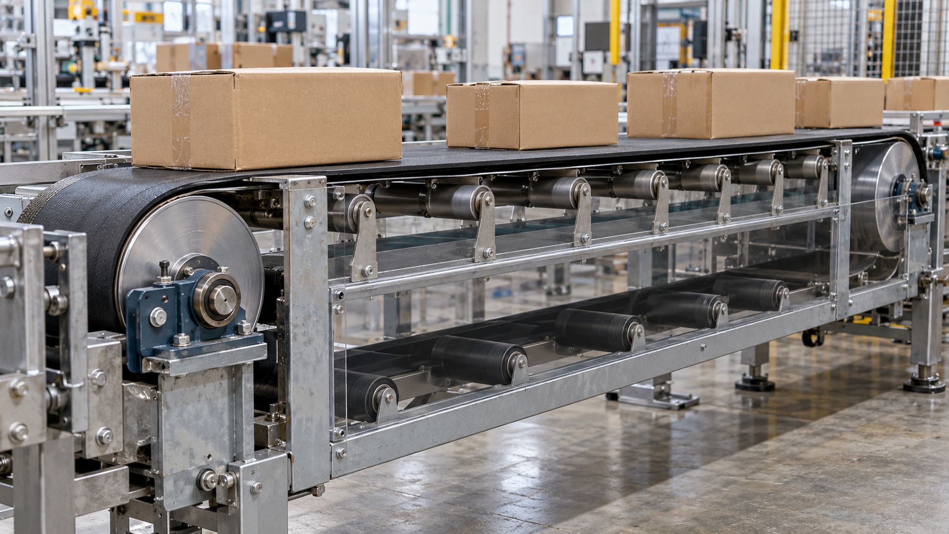 The belt carries the product on the upper run and travels back under the conveyor frame.
In a friction-drive conveyor, the drive pulley’s surface presses against the belt. The drive depends on suitable wrap and tension so the pulley can transfer torque without excessive slip. Other conveyor designs use a positive-drive belt whose teeth or features engage the pulley. The drive principle must match the belt construction; the two approaches do not use identical torque-transfer assumptions.
As the drive pulley turns, the upper belt run advances and moves the product. Carrying idlers or a slider bed support that run. At the far end, the tail pulley changes the direction of travel. The lower return run then travels back toward the drive pulley, supported by return rollers where the design requires them.
For many simple belt conveyors, the frame contains a drive pulley and an idler pulley at opposite ends, with the belt supported by rollers or a bed plate. Interroll’s commercial belt-drive design guidelines describe these basic arrangements and distinguish friction-drive from positive-drive systems.
The product does not necessarily touch each roller. On a belt conveyor, most products sit on the belt; the belt then transfers their weight to the support system. That differs from a roller conveyor, where the product itself rests directly on a series of rollers.
What Is the Difference Between a Belt Conveyor and a Roller Conveyor?
A belt conveyor supports products on a continuous belt; a roller conveyor supports them directly on rotating rollers.
| Design point | Belt conveyor | Roller conveyor |
|---|---|---|
| Product contact | Product contacts the belt | Product contacts the conveyor rollers |
| Small or irregular items | Often easier to support continuously | May need close roller pitch or a carrier |
| Drive method | Drive pulley moves the belt | Rollers may be driven by motor, chain, belt or gravity |
| Support elements | Idlers or a slider bed support the belt | Conveyor rollers form the carrying surface |
| Guide-wheel role | May guide belt edge or product path | May guide carriers or define a side path |
Some conveyors combine the approaches. A belt may run over a roller bed, or separate small guide wheels may limit lateral movement. When comparing systems, identify which surface supports the product and which rollers only guide or transfer motion.
Why Do Belt Tension and Tracking Matter?
The belt needs enough tension to transfer drive and stay controlled, while alignment keeps it from walking toward one side.
Too little tension can allow slip on a friction-drive pulley or unstable movement. Excessive tension raises loads on shafts, bearings, frame and belt and can increase wear. The right tension depends on belt type, drive design, load and operating conditions; it should come from the conveyor design rather than a generic number.
Tracking is the belt’s tendency to remain in its intended lateral path. A misaligned pulley, uneven loading, inconsistent belt splice, frame distortion or poor roller alignment can cause drift. A crowned or specially aligned pulley may be part of the solution, but the underlying geometry and loading still need review. A side guide roller should not be used to force a persistently misaligned belt back into position under constant heavy contact.
Bearings in the drive and idler pulleys carry the loads created by belt tension, product weight and operating forces. The direction and magnitude of the load matter more than the bearing name by itself. Our article on how belt or cable tension affects pulley bearing life explains why tension affects the bearing and support structure together.
Where Do Small Guide Rollers and Bearings Fit?
Small bearing rollers usually control a local contact or guide a moving edge; they do not replace the conveyor’s main drive or support rollers.
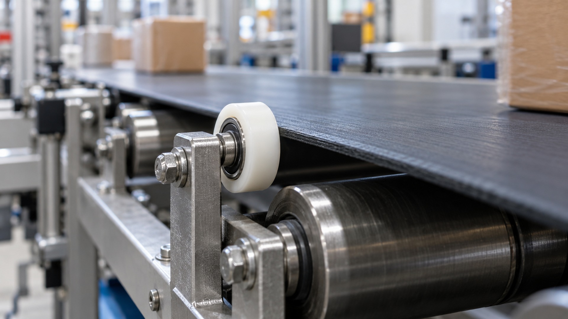 The small polymer wheel provides local guidance; the larger rollers beneath the belt support its main run.
A plastic-coated bearing roller can be useful where the machine needs a compact wheel to guide a product edge, centre a tube or carrier, limit lateral movement or provide a low-noise contact against a rail. The bearing provides the rotating interface around the axle; the plastic outer profile makes contact with the belt edge, product, cable or track.
The key is to identify the actual duty. A roller that touches a belt edge only during occasional drift is different from one that continuously pushes against the belt. Continuous side force can create heat, wear the belt edge and add axial load to the bearing. If the roller is intended to support product weight or serve as a primary idler, it needs a suitable purpose-designed assembly and validation for that load.
HUNE’s plastic-coated bearing guide roller specification for conveyor systems discusses contact duty, wheel profile, material, bearing retention and sample validation. For round rails, cords or tubes, a U-groove bearing roller is one profile to evaluate when the groove matches the mating part.
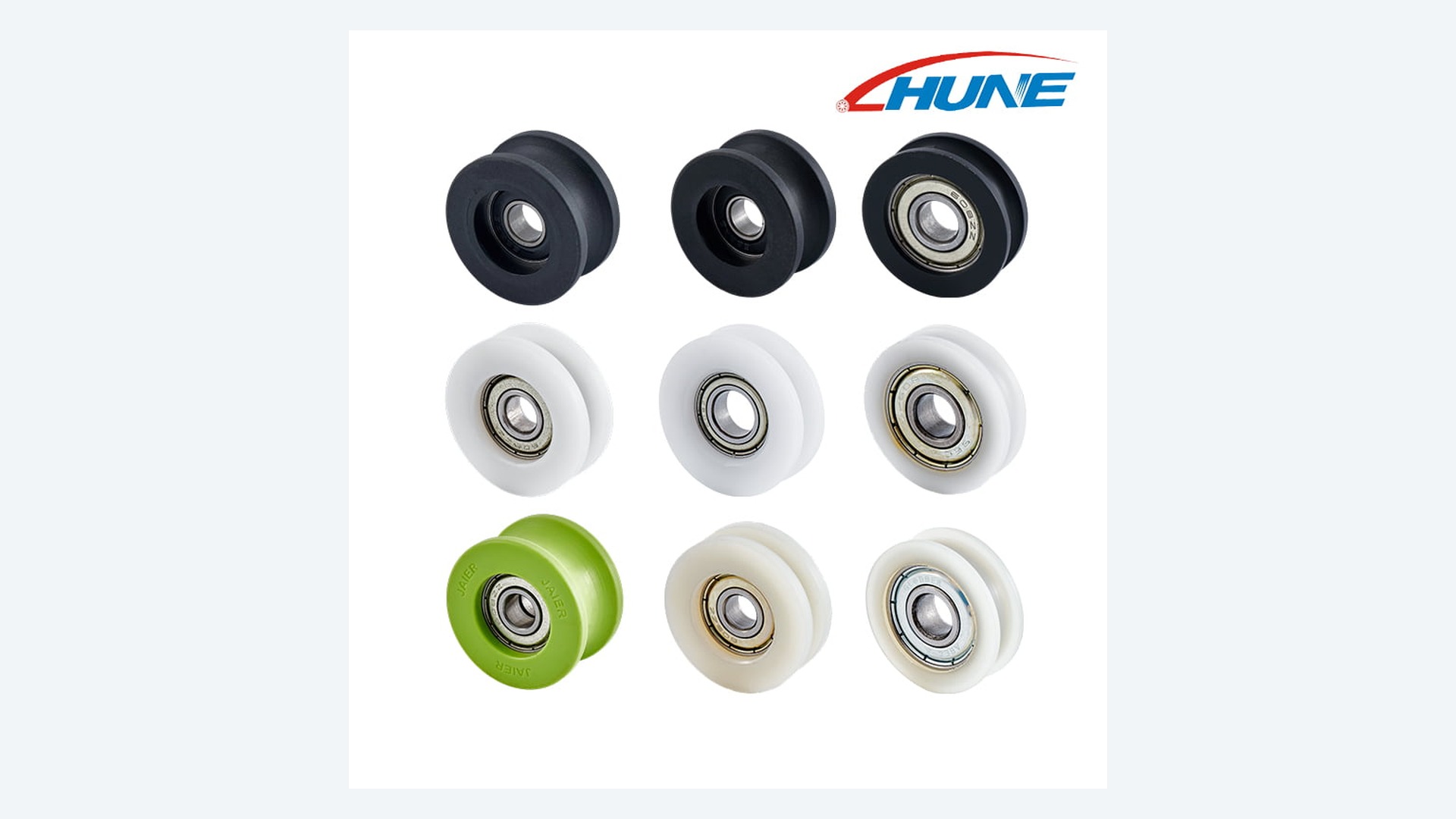 A real HUNE product image. A U-groove profile can guide a compatible round rail, cord or tube; it is not a general-purpose belt support roller.
What Should Engineers Consider When Selecting Conveyor Rollers?
Start with the contact and load path, then select dimensions, material and bearing arrangement.
For a carrying idler, the engineer considers belt width, roller length and diameter, product load, roller spacing, speed, impact and contamination. Interroll’s roller planning guide notes that the size and geometry of the conveyed item affect roller pitch and stability; its conveyor roller catalog gives product-specific planning guidance. CEMA’s standard listing for troughing and return idlers is a reference for bulk belt conveyor idlers.
For a smaller guide roller or plastic-coated bearing, I first ask:
- What exactly touches the wheel: belt edge, package, tube, wire or guide rail?
- Is contact continuous, intermittent or only a travel limit?
- Which direction carries the force, and is there side load or impact?
- What are the belt speed, cycle frequency and start-stop pattern?
- What are the available bore, outside diameter, width and bracket envelope?
- Does the wheel profile need to be flat, crowned, flanged or grooved?
- What contamination, moisture, oil, cleaning agent or temperature is present?
- Is low noise or surface protection important?
- How will the finished assembly be inspected and tested?
The functional dimensions are the effective running diameter, contact width, groove radius or flange clearance, bearing-seat position, bore, overall width and runout of the assembled wheel. The mating belt or track geometry should appear on the drawing or be supplied with a representative sample. Tight tolerances belong on dimensions that control contact and alignment, not automatically on every molded surface.
What Should an OEM Include in a Conveyor Roller RFQ?
A useful RFQ explains what the roller does in the machine and what it contacts.
Send the supplier:
- An assembly drawing showing the roller, axle, bracket and conveyor frame.
- The belt or mating rail section and the intended contact point.
- Functional dimensions, datums, tolerances and the drawing revision.
- Load direction, estimated force or load distribution, speed and duty cycle.
- Material and environmental requirements, including moisture and contaminants.
- Noise, surface marking and operating-force expectations.
- Sample quantity, pilot quantity and expected annual volume.
- The inspection method and installed test the sample must pass.
A photograph helps explain the installation, but it does not define a groove radius, bearing fit or side clearance. If there is no drawing yet, a physical sample plus the mating track or belt information can still support an initial review.
HUNE’s OEM development process covers drawing and sample review, tooling and production approval. For a custom conveyor guide roller, the trial should use the intended belt, bracket, speed and contact conditions. A free-spinning sample alone does not validate its behavior on the line.
Frequently Asked Questions
Do conveyor belts run directly on rollers?
Often the belt is supported by carrying idlers or a slider bed, but the product rides on the belt rather than touching the idlers. The exact arrangement depends on the belt and conveyor design. Roller conveyors are different because the product rests directly on the conveyor rollers.
What is the difference between a drive pulley and an idler pulley?
A drive pulley receives torque and moves the belt. An idler pulley turns or redirects the belt without serving as the primary drive. The exact naming can vary by design, so an equipment drawing should identify each pulley by its function.
Can a plastic-coated bearing roller support a conveyor belt?
It may be used for a designed support or guide duty if the complete roller, bearing, axle and bracket are sized and validated for the load. Many small plastic-coated bearing rollers are intended for local guidance rather than primary belt support. Confirm the supplier’s intended duty before specifying one.
Why does a conveyor belt move to one side?
Common contributors include pulley or roller misalignment, uneven loading, frame distortion, splice irregularity and contact with guides. A guide roller can limit movement in a suitable design, but continuous force against the belt edge may accelerate wear. The system geometry should be checked before changing the guide wheel.
What information should I send when sourcing a conveyor guide roller?
Send the assembly and mating profiles, the surface that contacts the wheel, functional dimensions, force direction, speed, duty cycle, environment, required material, sample quantity and expected production volume. If the wheel is part of an existing line, include photos and a physical sample when available.
Discuss a Conveyor Guide Roller Project with HUNE
HUNE supplies bearing rollers, plastic-coated wheels and custom roller assemblies for OEM equipment and guided-motion systems.
If you are developing a conveyor guide, send the belt or rail section, assembly space, contact duty, force direction, speed, environment and expected quantity. HUNE can review whether an existing roller profile is suitable or whether a custom wheel, bearing or mounting feature needs development.
Contact HUNE about a conveyor guide roller with the drawing revision and mating geometry so the first technical review starts from the actual application.
Engineering Recommendation
Treat a belt conveyor as a complete motion system. Define how the drive transfers torque, how the loaded and return runs are supported, how tension is controlled and what keeps the belt aligned. Then specify any small guide wheel according to its own contact, load and mounting duty.
For an OEM roller enquiry, include the belt or track section, the roller’s role, force direction, speed, environment, functional dimensions and sample test conditions. This prevents a guide wheel from being confused with a primary idler and gives the supplier enough information to recommend a credible assembly.



[…] a stop gate, adjustable guides or a transfer between machines. For the operating principles, see how conveyor belts work. The steps below help an OEM or integrator turn a production requirement into a reviewable […]
[…] exposure, cleaning method and any required material declarations. For related system context, see how conveyor belts work and how conveyor guide rollers keep products on […]