

Conveyors move products around curves by turning the carrying path while continuing to support and control the load. A roller curve uses rollers arranged along the arc, often with tapered surfaces to accommodate the different path lengths at the inside and outside of the turn. Belt and modular-belt curves carry products around a curved frame, often with side guides to limit drift. The right design depends on product size and base, load, curve radius, speed, orientation and transfer requirements.
A curve is not just a bent frame. The product must stay supported as the direction changes, and the conveyor must deliver it in a usable position for the next operation. Some systems let a carton turn naturally; others are designed to maintain its orientation more closely. Bearings support the rotating rollers or guide wheels, but the overall path is determined by the conveyor layout, drive and product-contact surfaces.
What changes when a conveyor takes a curve?
The inside and outside edges of a product travel different distances through the same turn. If a rigid carton follows a 90-degree curve, its outer edge covers a longer path than its inner edge. The conveyor must accommodate that difference without losing support or creating excessive rubbing, yaw or instability.
On a straight conveyor, the entire load can advance in roughly the same direction along parallel support surfaces. On a curve, each position across the conveyor width follows a different radius. Roller diameter, belt construction, speed and product friction all influence how the load responds. Side guides may contain the product, but they should not have to force an incompatible load through the turn.
How does a roller conveyor move products around a curve?
A roller curve supports the product on a series of rollers positioned around the turn. In a driven system, the rollers transfer motion from a belt, chain or other drive; in gravity layouts, the conveyor’s slope and the product’s motion provide travel. The exact drive arrangement varies by design.
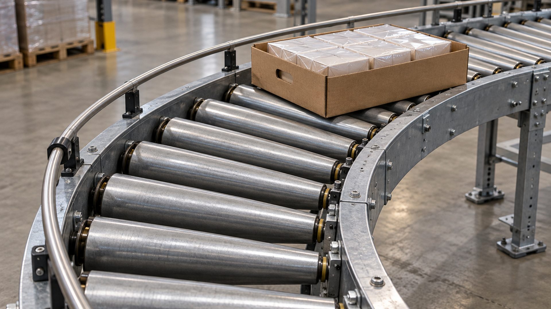
Many roller curves use tapered rollers or tapered sleeves. The larger effective diameter is toward the outside of the curve, where a product edge has farther to travel. Across a rotating roller, the change in effective diameter produces a corresponding change in surface speed. This can help the roller surface better match the inner and outer paths and reduce unwanted sliding as the product rounds the bend. On the straight infeed or return runs of a belt system, idler rollers support the belt; that support role is separate from the curve geometry.
Taper alone does not guarantee stable flow. The taper and roller spacing need to match the intended curve, product footprint and operating conditions. The carton or tray must bridge enough rollers to remain supported; a small or flexible item may need a different transfer design. Interroll describes tapered rollers for driven unit-load handling in curves, including cartons and trays, while its product data shows that curve suitability is tied to specific geometry and operating limits—not a universal roller choice.
Image placement 1 — after this section: Insert the generated image of a package on a curved roller conveyor to show how rollers support the load through the arc.
How do belt conveyors handle curves?
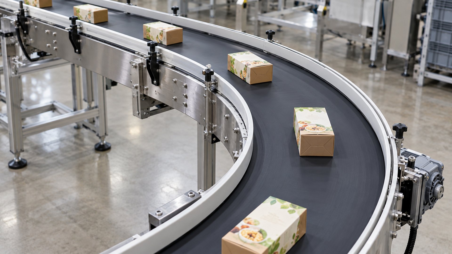
A curved belt carries the product continuously around a curved conveyor frame. The belt provides a broad, continuous support surface, which can help with small products or items whose bases do not bridge roller gaps well. The belt’s construction, support bed, drive and containment system are designed for the curved path.
Product behavior still depends on the belt-to-product interface. Friction, product shape and the curve geometry influence whether an item remains aligned, shifts toward the outside, or changes its orientation. Side rails can contain it, but excessive contact may scuff packaging or create drag. Some compact curve conveyors are designed to maintain product position through a turn; Dorner, for example, describes a compact curve system intended to keep a product’s leading edge consistent for downstream processing. That is a design-specific capability, not a behavior to assume for every curved belt.
Modular plastic belts can also be configured for curves. Their links articulate as the belt follows the frame, and the design needs to retain the belt while supporting the product. For a broader comparison of the conveying methods, see HUNE’s article on belt conveyors versus roller conveyors.
Image placement 2 — after this section: Insert the generated curved-belt image to contrast continuous belt support with a roller curve.
How do conveyors keep products stable through the turn?
Stability comes from matching the curve to the product and controlling the transition into and out of it. A narrow, tall carton can tip differently from a low tray; a round container can roll or rotate; a soft package can deform when side pressure is applied. The engineering review should consider the product’s center of gravity, base dimensions, mass distribution and contact surface, as well as the curve’s support and guides.
Guide rails or guide rollers can limit lateral drift and help present products to a labeler, printer, scanner or packing station. Their spacing should accommodate the expected product range without pinching it. A side guide is not the same as a belt-tracking device: one controls the product, while the other addresses the belt’s path. HUNE’s article on how conveyor guide rollers keep products on track explains that distinction in more detail.
The infeed and discharge are just as important as the curved section. Abrupt changes in speed, height, direction or support can rotate products or leave gaps where small items lose control. For that reason, I review a curve as part of the complete route: upstream spacing, curve, side guides, transfer points, sensors and the next machine.
Where do bearings and small rollers fit?
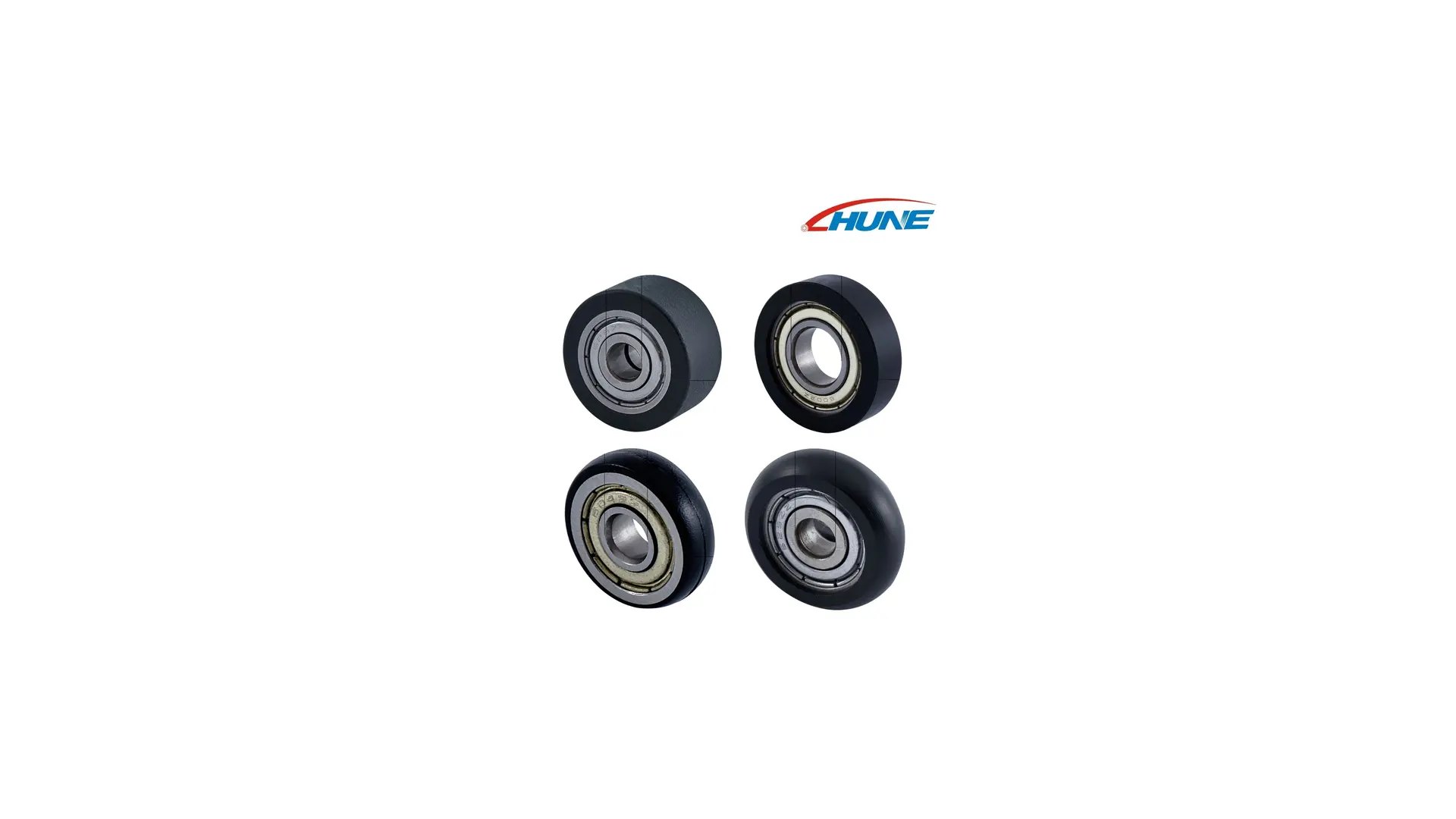
Bearings support the rotating parts; they do not determine the conveyor curve by themselves. A roller conveyor may use bearings in each roller assembly, while a compact guide mechanism may use a bearing-integrated wheel to contact a product, fixture or track. Those are distinct functions from the large carrying rollers or curved belt itself.
For compact guide components, the wheel profile, outside diameter, bearing bore, axle or stud, bracket, contact direction and mating surface need to be specified together. A HUNE conveyor guide system specification discusses the details that affect a plastic-coated bearing in compact guide applications. HUNE’s plastic-coated bearing rollers may be relevant when an OEM design calls for a compact bearing-integrated guide component; they should not be treated as a substitute for a complete industrial conveyor curve assembly.
Image placement 3 — after this section: Use the HUNE media-library photo as an example of a compact bearing-integrated roller component, not as a picture of a complete conveyor roller curve.
What should OEMs specify when selecting a conveyor curve?
Start with the product and route, then match the conveyor construction to the operating duty. A useful design brief or RFQ should include:
- Product drawings or samples, including length, width, height, base shape and the expected size range.
- Product mass, center-of-gravity concerns, packaging stiffness and surface sensitivity.
- Curve direction and angle, inner and outer radius, conveyor width and available floor space.
- Required throughput, line speed, spacing, accumulation behavior and direction of travel.
- Whether the product must preserve its orientation or may rotate through the turn.
- Conveyor type under consideration: driven roller curve, gravity roller curve, curved belt or modular-belt curve.
- Transfer heights, infeed and discharge geometry, side-guide position and downstream process requirements.
- Environment, cleaning method, dust or moisture exposure and noise constraints.
- For a custom guide wheel: profile, bearing dimensions, axle or stud, mounting geometry, load direction and inspection requirements.
- Prototype quantity, production volume, changeover range and validation conditions.
I would validate a proposed layout with the actual product at the smallest and largest expected sizes. Observe whether it stays supported, enters and exits cleanly, keeps the required orientation and reaches the downstream machine consistently. Do not infer performance from the curve radius alone; the product, speed, support pattern and guide arrangement all interact.
Frequently Asked Questions
Why are conveyor rollers tapered in a curve?
The outer side of a product follows a longer path than the inner side. A tapered roller changes its effective surface diameter across the width, creating different surface speeds that can better match those path lengths. The required taper and geometry depend on the specific curve and load.
Do products always keep the same orientation around a conveyor curve?
No. Some systems are designed to preserve product orientation closely, while others allow products to rotate or shift as they follow the arc. Belt friction, roller geometry, guides, product shape and the curve layout determine the result. Confirm the required leading-edge or label orientation for downstream operations.
Which is better for a curve: belt or roller conveyor?
Neither is universally better. A belt curve offers continuous support and may suit small or delicate items; roller curves can suit unit loads that bridge the roller spacing and may be designed with tapered elements for the turn. The choice depends on product dimensions, stability, line speed, transfers and the required path control.
Are conveyor curve rollers the same as guide rollers?
No. Curve rollers support and convey the load through the turn. Guide rollers or rails control lateral position at a side interface. A conveyor may use both, but their load paths and contact requirements differ.
Practical recommendation for OEM projects
Choose the curve from the product’s support and orientation needs, then specify bearings and guide rollers only for the interfaces they serve. Define the load envelope, curve geometry, speed, line spacing and downstream orientation requirement before comparing conveyor constructions. If the system includes a compact bearing-integrated guide wheel, provide its mating profile and mounting details separately.
For a component review, send HUNE the roller drawing, mating track or product-contact geometry, load direction, speed, environment, critical dimensions and expected volume through the HUNE contact page.


